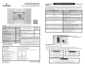
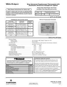
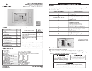
Handleiding Emerson 1F85CA-0471 Thermostaat
Handleiding voor je Emerson 1F85CA-0471 Thermostaat nodig? Hieronder kun je de handleiding gratis bekijken en downloaden als PDF in het Nederlands en/of Engels. Dit product heeft 2 veelgestelde vragen, 0 comments en heeft 0 stemmen. Is dit niet de handleiding die je zoekt, neem dan contact met ons op.
Is je product kapot en biedt de handleiding geen oplossing meer? Dan kun je voor reparatie gratis terecht bij Repair Café.
Handleiding
Loading…


Loading…
Beoordeling
Laat ons weten wat je van de Emerson 1F85CA-0471 Thermostaat vindt door een beoordeling achter te laten. Wil je je ervaringen met dit product delen of een vraag stellen? Laat dan een bericht achter onderaan de pagina.Meer over deze handleiding
We begrijpen dat het prettig is om een papieren handleiding te hebben voor je Emerson 1F85CA-0471 Thermostaat. Je kunt de handleiding bij ons altijd downloaden en daarna zelf printen. Indien je graag een originele handleiding wilt hebben, raden we je aan contact op te nemen met Emerson. Zij kunnen wellicht nog voorzien in een originele handleiding. Zoek je de handleiding van Emerson 1F85CA-0471 Thermostaat in een andere taal? Kies op de homepage je taal naar keuze en zoek daarna op het modelnummer om te zien of we deze beschikbaar hebben.
Specificaties
| Merk | Emerson |
| Model | 1F85CA-0471 |
| Categorie | Thermostaten |
| Bestandstype | |
| Bestandsgrootte | 1.31 MB |
Alle handleidingen voor Emerson Thermostaten
Meer handleidingen voor Thermostaten
Veelgestelde vragen over Emerson 1F85CA-0471 Thermostaat
Ons supportteam zoekt dagelijks naar nuttige productinformatie en antwoorden op veelgestelde vragen. Als er onverhoopt toch een onjuistheid tussen onze veelgestelde vragen staat, laat het ons dan weten via het contactformulier.
Wat is de dode zone van een thermostaat? Geverifieerd
Veel modernere thermostaten hebben een dode zone. Als de temperatuur minder dan ongeveer 4°C afwijkt van de ingestelde temperatuur, dan zal het systeem niet verwarmen of koelen. Deze zogenoemnde dode zone van de thermostaat voorkomt dat het systeem te vaak aan- en afslaat en bespaart zo energie.
Ik vind dit nuttig (1592) Lees meerWat is de beste locatie om een thermostaat te plaatsen? Geverifieerd
De beste plek voor een thermostaat is ongeveer 1,5 meter van de grond. Plaats de thermostaat niet in de buurt van een radiator of andere apparatuur die warmte afgeeft of in direct zonlicht. Kies een kamer die vaak wordt gebruikt. In veel gevallen is dit de woonkamer.
Ik vind dit nuttig (996) Lees meer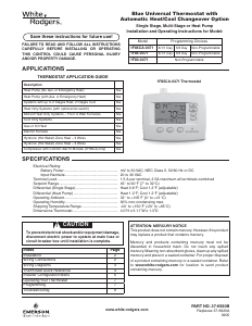
Praat mee over dit product
Laat hier weten wat jij vindt van de Emerson 1F85CA-0471 Thermostaat. Als je een vraag hebt, lees dan eerst zorgvuldig de handleiding door. Een handleiding aanvragen kan via ons contactformulier.