
*HQHUDOLWD
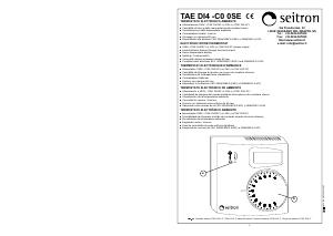
TAE ZN4 -C (Fig. 1) e’ un termostato a zona neutra progettato per
l’impiego con pompe di calore o con altri sistemi combinati di
riscaldamento e raffreddamento. Le uscite del dispositivo sono
costituite da due rele’ in scambio separati per il comando del
riscaldatore e del raffreddatore.
)XQ]LRQDPHQWR
Una volta impostato il valore del set-point il termostato chiudera’ il rele’
corrispondente allo stadio ’Riscaldamento’ o quello relativo allo stadio
’Raffreddamento’ a seconda che:
detti: Temperatura ambiente rilevata (°C)
Set-point (°C)
Ampiezza della Zona Neutra (°C)
sia:
(Rele' riscaldamento attivato)
oppure:
(Rele' raffreddamento attivato)
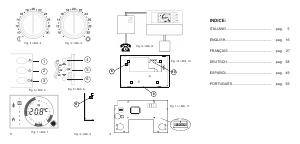
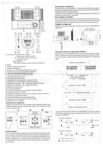
A seconda dello stadio attivato si accendera' il LED verde (1) per il
'Raffreddamento' o il LED rosso (2) per il 'Riscaldamento'. Il relativo
diagramma di attivazione e' riportato in Fig. 2.
Tramite la manopola di regolazione e' possibile impostare la
temperatura desiderata.
Tramite il trimmer (7) di Fig. 5 e' possibile regolare l'ampiezza della
zona neutra tra 1°C e 11°C come indicato sul circuito stampato.
E' possibile utilizzare una sonda a distanza (opzionale) in alternativa a
quella interna (fornita con il prodotto). Per attivare la sonda a distanza,
collegarla ai morsetti 9 e 10 e rimuovere il ponticello (8) indicato in Fig. 5.
,QVWDOOD]LRQH
Per installare il TAE ZN4 -C eseguire le seguenti operazioni:
Rimuovere la calotta plastica spostando verso l'interno,
con l'aiuto di un utensile, i due dentini plastici (3) posti
sul fianco destro
, (Fig. 4).
Fissare la base del termostato alla parete tramite le due sedi per
viti con interasse 60 mm.
Eseguire i collegamenti elettrici seguendo lo schema di Fig. 6.
Richiudere il termostato posizionando la calotta attentamente in
modo che i LED entrino nei fori appositi e successivamente
esercitando una pressione che faccia scattare i quattro dentini
plastici di fissaggio.
%ORFFRPDQRSROD
È possibile ridurre il campo entro cui ruota la manopola eseguendo i
passi:
Sollevare la manopola facendo leva con un cacciavite
nell'apposito invito.
Prelevare i cavalieri meccanici (4) parcheggiati a lato della sede
manopola e posizionarli (5) come nell'esempio di Fig. 3. In questo
modo (6) il campo di rotazione e' ridotto come nell'arco indicato.
&DUDWWHULVWLFKHWHFQLFKH
Alimentazione: TAE ZN4 MC: 230V~ -15% +10% 50Hz
TAE ZN4 2C: 24V~/= ±10%
Assorbimento: < 3VA
Campo di regolazione: Set-point: 6°C .. 30°C
Zona neutra: 1°C .. 11°C
Tipo sensore: NTC 4k7 ohm @ 25°C interno
Sonda a distanza: cod. STL NTS A150
Portata contatti: 5 (1) A @ 250V~
Tipo contatti: 2 x SPDT (scambio)
Grado di protezione: IP 30
Temperatura funzionamento: 0°C .. 40°C
Temperatura stoccaggio: -10°C .. +50°C
Limiti umidita': 20% .. 80% RH non condensante
Contenitore: Materiale: ABS autoestinguente V0
Colore: Bianco segnale (RAL 9003)
Dimensioni: 85 x 85 x 34 mm (L x A x P)
Peso: ~ 153 gr.
D $77(1=,21(
Nell’ottica di un continuo sviluppo dei propri prodotti, il costruttore si riserva il
diritto di apportare modifiche a dati tecnici e prestazioni senza preavviso.
Il consumatore è garantito contro i difetti di conformità del prodotto secondo la
Direttiva Europea 1999/44/ nonché il documento sulla politica di garanzia del
costruttore. Su richiesta è disponibile presso il venditore il testo completo della
garanzia.
2YHUYLHZ
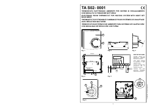
The TAE ZN4 -C (Fig. 1) is a neutral zone thermostat designed to be
used in conjunction with heat pumps or similar heating and cooling
combined systems. The device outputs consist of two double throw
relays which are separated for driving the heater and the cooler.
:RUNLQJ
Once the set-point is defined, the thermostat will activate the ’Heating’
or ’Cooling’ relay according to the following relations:
said: Current room temperature (°C)
Set-point (°C)
Neutral zone width (°C)
is:
(Heating relay active)
or:
(Cooling relay active)
According to the active stage, the green LED (1) is lit for 'Cooling' and
the red LED (2) is lit for 'Heating. The activation diagram is sketched in
Fig. 2.
Through the set-point knob the user can set the desired temperature.
Through trimmer (7) of Fig. 5 the user is allowed to adjust the neutral
zone width between 1°C and 11°C as indicated on the circuit board.
It is possible to connect a remote sensor (optional) in place of the
internal one (factory supplied). In order to activate the external sensor,
wire it at terminals 9 and 10 and then remove the jumper (8) located
on the circuit board (Fig. 5).
,QVWDOODWLRQ
For installation of TAE ZN4 -C follow these steps:
Remove plastic cover by moving to the inner side, through the
use of a tool, the two plastic teeth (3) located on the right side
of
the thermostat, (Fig. 4).
Fix the thermostat base plate to the wall through the two screw
holes with distance between axes of 60 mm.
Make electrical wirings according to the diagram of Fig. 6.
Close the thermostat by carefully positioning the cover so that the
LEDs match the relevant holes and then by slightly pressing the
cover in order to make the four plastic teeth snapping.
.QREURWDWLRQOLPLWDWLRQ
It is possible to limit the rotation range for the set-poin knob by
following these steps:
Remove the knob by tilting it, eventually with the help of a
screwdriver placed in the slot.
Pick up the plastic pins (4) parked at one side of the knob area
and set them (5) as in the example of Fig. 3. In this example (6)
the rotation range is reduced as in the shown angle.
7HFKQLFDOIHDWXUHV
Power supply: TAE ZN4 MC: 230V~ -15% +10% 50Hz
TAE ZN4 2C: 24V~/= ± 10%
Power absorption: < 3VA
Regulation range: Set-point: 6°C .. 30°C
Neutral zone: 1°C .. 11°C
Sensor type: NTC 4k7 ohm @ 25°C internal
Remote sensor: cod. STL NTS A150
Contact rating: 5 (1) A @ 250V~
Contact type: 2 x SPDT
Protection grade: IP 30
Work temperature range: 0°C .. 40°C
Stock temperature range: -10°C .. +50°C
Humidity limits: 20% .. 80% RH non condensing
(1*/,6+
,7$/,$12
TAE ZN4 MC0 0AN 012248B4 160206
*pQpUDOLWp
Le TAE ZN4 -C (Fig. 1) est un thermostat à zone neutre conçu pour
l'utilisation avec une pompe à chaleur ou avec d'autres systèmes
combinés de chauffage et de conditionnement. Les sorties du
dispositif sont constituées de deux relais en échange, séparés pour la
commande du chauffage et du refroidisseur.
)RQFWLRQQHPHQW
Une fois réglée la valeur du set-point, le thermostat fermera le relais
correspondant à l'état "chauffage" ou celui relatif au "refroidissement"
selon que:
donnée: Température ambiance relevée (°C)
Set-point (°C)
Grandeur de la zone neutre (°C)
soit:
(Relais chauffage activé)
ou:
(Relais conditionnement activé)
Selon l'état activé, le LED vert (1) s'allumera pour le "refroidissement"
ou le led rouge (2) pour le "conditionnement". Le diagramme
d'activation est reporté en Fig. 2.
Grâce au bouton de réglage, il est possible de régler la température
désirée.
Grâce au trimmer (7) de la Fig. 5, il est possible de régler la grandeur
de la zone neutre entre 1°C et 11°C comme indiqué sur le circuit
imprimé.
Il est possible d'utiliser une sonde à distance (en option) en alternative
à celle interne (fournie avec le produit). Pour activer la sonde à
distance, la relier aux borniers 9 et 10 et retirer le cavalier (8) indiqué
sur la Fig. 5.
,QVWDOODWLRQ
Pour installer le TAE ZN4 -C (Fig. 1) suivre les opérations suivantes:
Soulever le bouton en faisant levier avec un tourne-vis. Retirer la
calotte de plastique en appuyant vers l'intérieur sur les deux petites
dents de plastique (3) situées sur les côtés droit
, (Fig. 4).
Fixer la base du thermostat sur la paroi grâce aux trous prévus à
cet effet (inter axe 60 mm).
Suivre les instructions pour les branchements électriques selon le
schéma de la Fig. 6.
Refermer le thermostat en repositionnant soigneusement la calotte
de sorte que les LED se positionnent sur es emplacements prévus à
cet effet et effectuer une légère pression afin d'enclencher les 4 petites
dents de fixation.
%ORFDJHGXERXWRQ
Il est possible de réduire le champs de réglage du bouton:
Soulever le bouton en faisant levier avec un tourne-vis;
Case: Material: ABS self-extinguishing V0
Color: Signal white (RAL 9003)
Size: 85 x 85 x 34 mm (W x H x D)
Weight: ~ 153 gr.
D :$51,1*
In the view of a constant development of their products, the manufacturer reser-
ves the right for changing technical data and features without prior notice. The
consumer is guaranteed against any lack of conformity according to the Europe-
an Directive 1999/44/EC as well as to the manufacturer’s document about the
warranty policy. The full text of warranty is available on request from the seller.
Extraire les cavaliers mécaniques (4) situés sur les côtés
du bouton et les positionner (5) comme dans l'exemple de la
Fig. 3. De cette façon, le champs de rotation (6) est réduit dans
l'arc choisi.
&DUDFWpULVWLTXHVWHFKQLTXHV
Alimentation: TAE ZN4 MC: 230V~ -15% +10% 50Hz
TAE ZN4 2C: 24V~/= ±10% 50Hz
Puissance électrique: < 3VA
Champ de réglage: Set-point: 6°C .. 30°C
Zone neutre: 1°C .. 11°C
Type de capteur: NTC 4k7 ohm @ 25°C interne
Sonde à distance (en option): cod. STL NTS A150
Portée des contacts: 5 (1) A @ 250V~
Type des contacts: 2 x SPDT
Degré de protection: IP 30
Temp. de fonctionnement: 0°C .. 40°C
Temp. de stockage: -10°C .. +50°C
Limite d’humidité: 20% .. 80% RH non condensée
Boîtier: Matière: ABS V0 auto extinctible
Couleur: Blanc de sécurité (RAL 9003)
Dimensions: 85 x 85 x 34 mm. (L x H x P)
Poids: ~ 153 gr.
D $77(17,21
Dans l’optique d’un développement continu de ses produits, le constructeur se
réserve le droit d’apporter sans préavis, des modifications aux données
techniques et aux prestations de ces derniers. Selon la Directive Européenne
1999/44/ et le document qui reporte la politique de garantie du constructeur, le
consommateur est protégé contre les défauts de conformité du produit. Le texte
complet de la garantie est disponible auprès du vendeur sur demande.
)5$1d$,6
(63$12/
*HQHUDOLGDGHV
El TAE ZN4 -C (Fig. 1) es un termostato a zona neutra proyectado
para la utilización con bombas de calor o con otros sistemas
combinados de calefacción o refrigeración. Las salidas del dispositivo
están constituidas por dos relés de intercambio separados por el
mando del calefactor o del refrigerador.
)XQFLRQDPLHQWR
Una vez fijado el valor del set-point el termostato cerrará el relé
correspondiente al estado “calefacción” o al relativo del estado de
refrigeración si:
Dichos: Temperatura ambiente relevada (°C)
Set –point (°C)
Amplitud de la zona neutra (°C)
Sean:
(Relé calefacción activado)
o bien
(Relé refrigeración activados)
Según el estado activado se encenderá el LED verde (1) para la
“Refrigeración” o el LED rojo (2) para la “Calefacción”. El relativo
diagrama de activación se encuentra en la Fig. 2.
Mediante el mando de regulación es posible fijar la temperatura
deseada.
Mediante el trimmer (7) de la Fig. 5, es posible regular la amplitud de
la zona neutra entre 1°C y 11°C como se indica en el circuito impreso.
Es posible utilizar una sonda a distancia, (opcional) en alternativa a la
interna, (provista con el producto). Para activar la sonda a distancia,
conectarla a los bornes 9 y 10 y remover el puentecito (8) indicado en
Fig. 5.
TAE ZN4 MC0 0AN 012248C4 160206

Praat mee over dit product
Laat hier weten wat jij vindt van de Seitron TAEZN4MC Thermostaat. Als je een vraag hebt, lees dan eerst zorgvuldig de handleiding door. Een handleiding aanvragen kan via ons contactformulier.