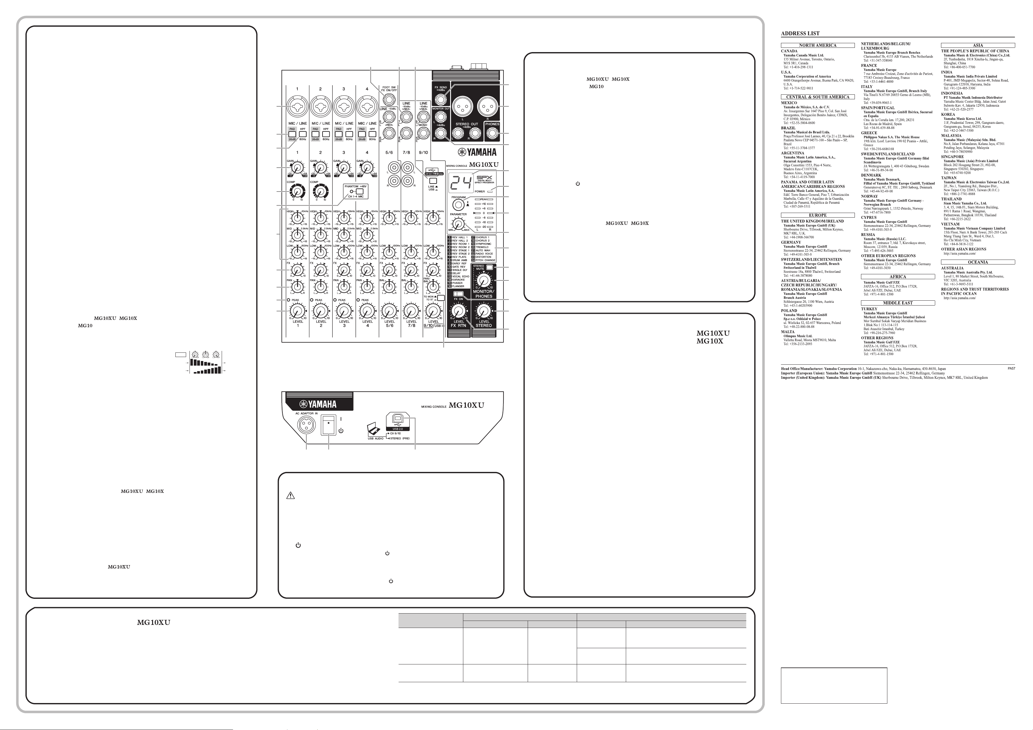
Controls and FunctionsControls and Functions
Rear panel
Caution
The unit may heat up by as much as 15 to 20°C while the power is on. This is normal. Please note that since the
panel temperature may exceed 50°C in ambient temperatures higher than 30°C, you should exercise caution to
prevent burns.
E
[AC ADAPTOR IN] connector
For connecting the supplied AC power adaptor.
F
[ /I] switch
For turning the power of the unit to standby ( ) and on (I). The [POWER] LED
(
on the top panel
lights when the switch is set to on (I).
NOTE
•
Rapidly switching the unit between on and standby in succession can cause it to malfunction. After
setting the unit to standby, wait for about six seconds before turning it on again.
•
Even when the switch is in the standby ( ) position, electricity is still flowing to the unit. If you do
not plan to use the unit for a while, be sure to unplug the AC power adaptor from the outlet.
Top panel
Rear panel
# $
@
E F G
7
Top panel Channel section (Input:
1
to
$
)
1
[MIC/LINE] mono input jacks (channels 1-4)
For connecting a microphone, instrument, or audio device (CD player, etc.) to the unit. These jacks support
both XLR and phone plugs.
2
[PAD] switches
Turning the switch on (
O
) will attenuate the sound input to the unit. If you hear distortion or the
[PEAK] LED
)
lights, turn the switch on (
O
).
NOTE
Turn the [LEVEL] knob to "0" (minimum) before toggling the [PAD] switch on (
O
) and off (
N
).
Otherwise, noise may be produced.
3
[HPF] (High-Pass Filter) switches
Turning the switch on (
O
) will apply a high-pass filter that attenuates frequencies below 80 Hz.
When speaking into the microphone, you may want to turn this switch on (
O
), in order to reduce
unwanted vibration and wind sound received by the microphone.
4
[GAIN] knobs
Determines the basic volume for each of the channels 1 to 4. Adjust these so that the correspond-
ing [PEAK] LEDs
)
flash briefly when singing or playing the loudest.
5
[COMP] knobs
Adjusts the amount of compression applied to the channel. As the knob is turned to the right, the
threshold, the ratio, and the output level are adjusted at the same time.
Threshold: +22 dBu to -8 dBu; Ratio: 1:1 to 4:1; Output level: 0 dB to +7 dB;
Attack time: approx. 25 msec; Release time: approx. 300 msec
6
[PHANTOM +48V] switch/LED
When this switch is on (
O
), the LED lights indicating that the unit supplies DC+48 V phantom
power to the XLR plugs of the [MIC/LINE] mono input jacks
1
. Turn this switch on when using a
phantom-powered condenser microphone.
NOTICE
Be sure to leave this switch off (
N
) if you do not need phantom power. Follow the important precautions below, in
order to prevent noise and possible damage to external devices as well as the unit when you operate this switch.
• Be sure to leave this switch off when connecting a microphone or other device that does not require phantom
power to channels 1 to 4.
• Do not connect/disconnect a cable to/from channels 1 to 4 while this switch is on.
• Turn the [LEVEL] knobs of channels 1 to 4 to the minimum before operating this switch.
7
Equalizer (EQ) knobs
Adjust the tone by using the [HIGH] (high frequency band), [MID] (middle frequency band), and
[LOW] (low frequency band) knobs. If you do not need to adjust the tone, set the knob to the “
D
”
(flat) position.
8
[FX] (effect) knobs
[AUX] knobs
[FX]: Adjusts the volume sent from each channel to the internal effect and the [FX SEND] jack.
[AUX]: Adjusts the volume sent from each channel to the [AUX SEND] jack.
9
[PAN] knobs (channels 1 to 4)
[BAL] knobs (channels 5/6 and 7/8)
[PAN/BAL] knobs (channels 9/10)
[PAN]: Adjusts the volume balance of each channel sent to
the stereo bus, and determines the positioning of the sound image between left and right (stereo
L/R). When the knob is located at the 12 o’clock position, the channel’s sound will be sent to the
stereo bus channels (L and R) at the same volume. In this case, the sound image is positioned at
the center.
[BAL]: Determines the volume balance of the stereo channels (5/6 to 9/10) (L/R) sent to the stereo
bus. When the knob is located at the 12 o’clock position, the sound of the stereo channels will be
sent to the stereo bus channels (L and R) at the same volume respectively.
[PAN/BAL]: Provides both [PAN] and [BAL] functions. You can use this as a [PAN] control when
sound is input to the [LINE] (L/MONO) jack, and as a [BAL] control when sound is input to both
[LINE] (L) and [LINE] (R) jacks.
)
[PEAK]LED
Lights when the volume of input and/or post-equalizer sound is too high (when reaching 3 dB be-
low clipping). If it is lit frequently, turn the [GAIN] knob
4
to the left to lower the volume.
!
[LEVEL] knobs
For adjusting the volume balance among the channels. Generally, set this to the “
L
” position.
@
[TO MON
N
/TO ST
O
] switch
For selecting the output destination of the input sound to channels 9/10. Normally set this switch
to [TO ST
O
]. When you use the MG10XU with a computer connected to the [USB 2.0] terminal,
toggle this switch according to your specific application, referring to the chart in “Rear panel USB
section.”
#
[LINE] stereo input jacks (channels 5/6 to 9/10)
For connecting line-level devices such as an electric keyboard or an audio device. These jacks
support phone plugs and RCA-pin plugs.
NOTE
Regarding input to channels 5/6 and 7/8, if both phone and RCA-pin jacks are used at the same
time, the phone jack will take priority.
$
[LINE
N
/USB
O
] switch
Toggles the sound source input to channels 9/10. When the switch is set to [LINE
N
], the source
will be the [LINE] stereo input jack
#
, and when set to [USB
O
], the source will be the [USB 2.0]
terminal
G
.
BAL
LINE L
LINE R
Stereo bus L
Stereo bus R
Top panel Master section (Input:
%
to
D
)
%
[FX SEND] jack :
[AUX SEND] jack:
For connecting an external effects unit or a monitor system for players. This phone-plug jack out-
puts the sound adjusted with the [FX] knob or [AUX] knob respectively.
^
[STEREO OUT] jacks
For connecting a powered speaker or powered amp. These jacks support both XLR and phone
plugs.
&
[PHONES] output jack
For connecting a set of headphones. This jack supports a stereo phone plug.
*
[MONITOR OUT] jacks
For connecting a monitor system for operators. These jacks support phone plugs.
(
[POWER] LED
Lights when the [ /I] switch on the rear panel is set to on (pressed to the [I] position).
A
Level meter
The L and R meters show the level (volume) of the signal output from the [STEREO OUT] jacks by
seven steps; “PEAK” (+17), “+10”, “+6”, “0”, “-6”, “-10”, and “-20” dB. If the “PEAK” lamp continu-
ously lights in red, turn the [STEREO LEVEL] knob to the left to lower the volume.
B
[STEREO MUTE] switch
Turning the switch on (
O
) will mute the sound of stereo bus from the output of [MONITOR OUT]
jacks or [PHONES] jack. In this state, when setting the [TO MON
N
/TO ST
O
] switch for channels
9/10 to [TO MON
N
], you can hear the sound only from channels 9/10. When using the MG10XU,
for details about the switch, see the “Rear panel USB section” below.
C
[MONITOR/PHONES] knob
Adjusts the volume output to the [MONITOR OUT] jacks and the [PHONES] jack.
D
[STEREO LEVEL] knob
Adjusts the overall volume output from the [STEREO OUT] jacks.
Rear panel USB section
G
[USB 2.0] terminal
For connecting to a computer via a commercially available USB 2.0 cable. (This
product does not come with a cable.) The sound of the stereo bus is output to the
computer. (The [STEREO LEVEL] knob
D
does not affect the sound.) For inputs
and outputs to/from the computer, you may need a dedicated USB driver. Check
and download the driver at the following Yamaha web site and install it to the com-
puter before use.
http://www.yamahaproaudio.com/mg_xu/
Application
Selection of the output destination sent from channels 9/10 Selection of the monitoring sound with the headphones/monitor speaker
[TO MON
N
/TO ST
O
] switch Output destination [STEREO MUTE] switch Monitoring sound
When recording with DAW
software while listening to the
playback sound from a com-
puter.
[TO MON
N
]*1
[MONITOR OUT] jack*2
[PHONES] jack*2
On (
O
)
The direct sound (of the instrument) input to the MG10XU will be
muted, allowing you to hear the playback sound only from the
DAW.
(Direct monitoring: Off )
Off (
N
)
You can hear the mixed sound of the direct instrument sound
input to the MG10XU and the playback sound from the DAW.
(Direct monitoring : On)
When playing back sound from
a computer. For example: BGM
playback, Internet broadcasting
[TO ST
O
]
Stereo bus
è
[STEREO OUT] jack
Normally set to Off (
N
)
You can hear the mixed sound of the instrument sound input to
the MG10XU and the playback sound from a computer.
*1 NOTICE If you set the switch to [TO ST
O
] when you use the DAW software, a loop may be produced, possibly resulting in feedback.
*2 The audio signal cannot be sent to the computer because it does not pass through the stereo bus.
Manual Development Group
© 2021 Yamaha Corporation
Published 11/2021 MWEM-A0
Yamaha Pro Audio global website
http://www.yamahaproaudio.com/
Yamaha Downloads
https://download.yamaha.com/
For details of products, please contact your nearest Yamaha representative or the authorized distributor listed below.
2
Top panel
Internal effect section (Output:
1
to
7
)
1
Display
Indicates the effect program number selected with the [PROGRAM] knob
2
. The number flashes
during selection; however, if several seconds pass without a selection being made, the program
returns to the last number selected.
2
[PROGRAM] knob
Selects one of the 24 internal effects from 1-24. Turn the knob to select the desired effect program,
and then press the knob to actually set it. For instructions on how to apply the effect, see the sec-
tion “Applying effects” on the reverse side.
NOTE
Turning the knob while pressing it down also allows you to simultaneously select and set the ef-
fect program (without needing to press the knob finally to set it).
3
[PARAMETER] knob
Adjusts the parameter (depth, speed, etc.) for the selected effect. The last value used with each ef-
fect program is saved. For details about the parameter, see the “Effect programs” list on the reverse
side.
NOTE
When you change to a different effect program, the unit automatically restores the value that was
previously used with that program (regardless of the current position of the [PARAMETER] knob).
Once you turn the [PARAMETER] knob, the value of current knob position will become valid.
4
Effect program list
This is the list of the internal effect programs. For details about the programs, see the “Effect pro-
grams” list on the reverse side.
5
[FX ON] switch
When the switch is turned on (
O
), the switch lights indicating the internal effect is active. If you turn
off the internal effect with the foot switch when the switch is on (
O
), the LED of the switch flashes.
6
[FX RTN LEVEL] knob
Adjusts the volume of the internal effect sound.
7
[FOOT SW] jack
For connecting an optionally available unlatched type footswitch, such as the Yamaha FC5. When
the [FX ON] switch
5
is turned on (
O
), the internal effects can be toggled on/off with the footswitch
as needed with your foot. This jack supports a phone plug.
n
Using the unit connected to a computer
Set the [LINE
N
/USB
O
] switch of channels 9/10 to [USB
O
]. Depending on your
particular application, you can specify the output destination and monitoring
sound by selecting the settings of the [TO MON
N
/TO ST
O
] switch
@
for chan-
nels 9/10 and the [STEREO MUTE] switch
B
. For details, see the chart at right.
n
Adjusting the playback volume from a computer (Attenuator)
1. Press the [PROGRAM] knob five times consecutively to display the attenua-
tion value (dB). 2. Turn the [PROGRAM] knob to set it between -24 dB to 0 dB
(minus sign is not displayed). 3. Press the [PROGRAM] knob again to exit the
setting.
When the attenuator is enabled, the dot lights at the lower right of the display.


Praat mee over dit product
Laat hier weten wat jij vindt van de Yamaha MG10XU Mengpaneel. Als je een vraag hebt, lees dan eerst zorgvuldig de handleiding door. Een handleiding aanvragen kan via ons contactformulier.