
TroubleshootingTroubleshooting
Power does not come on.
F
Did you properly plug the power adaptor into an appropriate AC outlet?
F
Did you rmly and securely connect the power plug?
No sound.
F
Did you turn on the powered speaker or the power amp?
F
Did you properly connect the microphones, external devices, and speakers?
F
Are any connecting cables shorted or damaged?
F
Have the [GAIN] knobs and [LEVEL] knobs of all relevant channels as well as the [STEREO LEVEL]
knob been set to appropriate levels?
F
Are the [PAD] switches turned on (
O
)?
Turn the switch off (
N
). If the volume of sound source is too soft, turning on the switch may result in
no audible sound.
F
Is the [STEREO MUTE] switch turned on (
O
)? (
/ )
If the switch is turned on (
O
), the sound is not output from the [MONITOR OUT] jack/[PHONES]
jack, since this mutes the sound of the stereo bus.
Sound is faint, distorted, or noisy.
F
Are the [PEAK] LEDs lit?
Lower the [GAIN] knobs of all relevant channels, or turn on (
O
) the [PAD] switches.
F
Are the [GAIN] knobs and [LEVEL] knobs of all relevant channels, and the [STEREO LEVEL] knob
set too high?
F
Are the “PEAK” (red) lamps of the level meter lit?
Set the [LEVEL] knobs of all relevant channels and the [STEREO LEVEL] knob to appropriate lev-
els.
F
Is the volume from the connected device too loud?
Lower the volume of the connected device.
F
Is the [TO MON
N
/TO ST
O
] switch set to [TO ST
O
]? (
/ )
If you set the switch to [TO ST
O
] when you use the DAW software, a loop may be produced
depending on the setting of DAW software, possibly resulting in feedback. When recording while
listening to the sound via a computer, be sure to set the switch to [TO MON
N
].
The sound of vocals and speech isn’t clear enough.
F
Turn on (
O
) the [HPF] switches.
The sound becomes clearer.
F
Adjust the equalizer knobs (example: lower the [LOW] knobs, raise the [HIGH] knobs).
No effect is applied
( / )
F
Did you turn on (
O
) the [FX ON] switch?
F
Did you set the [FX RTN LEVEL] knob to an appropriate level?
F
Are the [LEVEL] knobs and [FX] knobs of all relevant channels raised enough?
General Specifications
Frequency Response Input to STEREO OUT
+0.5 dB/-1.0 dB (20 Hz to 48 kHz), refer to the nominal output level @ 1 kHz, GAIN knob:
Min
Total Harmonic
Distortion(THD+N)
Input to STEREO OUT
0.02 % @ +14 dBu (20 Hz to 20 kHz), GAIN knob: Min
0.003 % @ +24 dBu (1 kHz), GAIN knob: Min
Hum & Noise *1
(20 Hz to 20 kHz)
Equivalent Input Noise -128 dBu (Mono Input Channel, Rs: 150 Ω, GAIN knob: Max)
Residual Output Noise -102 dBu (STEREO OUT, STEREO LEVEL knob: Min)
Crosstalk (1 kHz) *2 -83 dB
Input Channels 10 channels; Mono [MIC/LINE]: 4, Stereo [LINE]: 3
Output Channels STEREO OUT: 2, PHONES: 1, MONITOR OUT: 1, AUX (FX) SEND: 1
Bus Stereo: 1, AUX (FX): 1
Input Channel
Function
PAD CH 1 – CH 4 26 dB
HPF CH 1 – CH 4 80 Hz, 12 dB/oct
COMP CH 1 – CH 2
1-knob compressor
Threshold: +22 dBu to -8 dBu, Ratio: 1:1 to 4:1,
Output level: 0 dB to 7 dB, Attack time: approx. 25 msec,
Release time: approx. 300 msec
EQ
CH 1 – CH 9/10 HIGH: Gain: +15 dB/-15 dB, Frequency: 10 kHz shelving
CH 1 – CH 4 MID: Gain: +15 dB/-15 dB, Frequency: 2.5 kHz peaking
CH 1 – CH 9/10 LOW: Gain: +15 dB/-15 dB, Frequency: 100 Hz shelving
PEAK LED CH 1 – CH 4
LED turns on when post EQ signal reaches 3 dB below clipping
(+17 dBu)
Level Meter
Post STEREO LEVEL
Knob
2x7 -segment LED meter [PEAK (+17), +10, +6, 0, -6, -10, -20 dB]
Internal Digital
Effects
(MG10XU/MG10X)
SPX Algorithm 24 programs
USB Audio
(MG10XU Only)
2 IN / 2 OUT
USB Audio Class 2.0 compliant
Sampling Frequency: Max 192 kHz, Bit Depth: 24-bit
Phantom Power Voltage +48 V
Power Supply Adaptor
PA-10 ( AC 38 VCT, 0.62 A, Cable length = 3.6 m), or equivalent recommended by
Yamaha
Power Consumption 22.9 W
Dimensions (W×H×D) 244 mm×71 mm×294 mm (9.6"x 2.8"x 11.6")
Net Weight MG10XU, MG10X: 2.1 kg (4.6 lbs.), MG10: 1.9 kg (4.1 lbs.)
Optional Accessory Mic Stand Adaptor: BMS-10A
Operating Temperature 0 to +40 °C
*1 Noise is measured with A-weighting filter. *2 Crosstalk is measured with 1 kHz band pass filter.
* The contents of this manual apply to the latest specifications as of the publishing date. To obtain the latest manual, access the Yamaha website
then download the manual file.
Mounting to a Microphone StandMounting to a Microphone Stand
The unit can be mounted onto a microphone stand as illustrated
at right, by using the optionally available Yamaha BMS-10A
microphone stand adaptor. For instructions on mounting, refer to
the BMS-10A Owner’s Manual.
0 dBu = 0.775 Vrms Output impedance of signal generator (Rs) = 150 Ω
All level knobs are nominal if not specified.
1
Welcome
Thank you for purchasing the Yamaha MG10XU/MG10X/MG10 Mixing Console.
Please read this manual thoroughly to get the most out of the product and ensure long-term,
trouble-free use. After reading this manual, keep it readily available for future reference.
• In this manual, “ ”, “ ”, and “ ” are used to indicate contents unique to the
MG10XU, MG10X, and MG10, respectively. The contents are common if those logos are not indicated.
• In this manual, all panel illustrations show the MG10XU panel, unless otherwise specified.
• The illustrations as shown in this manual are for instructional purposes only, and may appear somewhat
different from those on your device.
• Steinberg and Cubase are registered trademarks of Steinberg Media Technologies GmbH.
• The company names and product names in this manual are the trademarks or registered trademarks of
their respective companies.
Included Accessories
• AC power adapter
• Precautions: Please read this thoroughly before using the product. Warranty information for Europe is
also included in this leaflet.
• Technical Specifications (English only): Includes block diagram, dimensions, general specifications,
and input/output characteristics.
• Cubase AI Download Information (MG10XU only): Contains the access code necessary for download-
ing the Steinberg DAW software “Cubase AI.” Visit the following Yamaha website for downloading and
installing Cubase AI, and information on making necessary settings.
http://www.yamahaproaudio.com/mg_xu/
• Owner’s manual (this leaflet)
EN
VFN2790
MIXING CONSOLE
Owner’s Manual
If there is no sound:
•
Are the [PAD] switches turned on (O)? Turn the switches off (N).
•
Are the [GAIN] knobs raised enough?
•
Raise the volume of the connected instruments or audio devices.
If the sound is distorted:
•
Are the [PAD] switches turned off (N)? Turn the switches on (O).
•
Are the [GAIN] knobs raised too high? Turn the knobs to the left to lower the volume.
•
Lower the volume of the connected instruments or audio devices.
Applying Effects Applying Effects
The MG10XU and the MG10X feature high-quality built-in signal processing effects that are in
the same league as our famed SPX effect processor series. Applying effects (as described
below) allows you to simulate the acoustics of different performance environments.
5
4
3
Effect program list
1, 2
1
1 Turn the [PROGRAM] knob to select a desired effect program number from the
effect program list.
The currently selected effect program number flashes on the display.
NOTE
For details about the effect programs, refer to the “Effect Programs” list below.
2 Press the [PROGRAM] knob to actually select it.
The desired effect program is selected.
3 Turn on (O) the [FX ON] switch.
4 Set the [FX RTN LEVEL] knob to the “L” position.
5 Turn the [FX] knob of the channel to which you want to apply the effect to ad-
just the effect amount.
Effect Programs
No. Program Parameter Description
1 REV HALL 1 Reverb Time
Reverb simulating a large space such as a concert hall.
2 REV HALL 2 Reverb Time
3 REV ROOM 1 Reverb Time
Reverb simulating the acoustics of a small space (room).
4 REV ROOM 2 Reverb Time
5 REV STAGE 1 Reverb Time
Reverb simulating a large stage.
6 REV STAGE 2 Reverb Time
7 REV PL ATE Reverb Time
Simulation of a metal-plate reverb unit, producing a more
hard-edged reverberation.
8 DRUM AMB Reverb Time A short reverb that is ideal for use with a drum kit.
9 EARLY REF Room Size
An effect which isolates only the early reflection components
from reverberation, creating a ‘flashier’ effect than conven-
tional reverb.
10 GATE REV Room Size
An effect which cuts halfway the tail-end of the reverbera-
tion, making a more powerful sound.
11 SINGLE DLY Delay Time
An effect which repeats the same sound only once. Shorten-
ing the delay time produces a doubling effect.
12 DEL AY Delay Time Feedback delay adding multiple delayed signals.
13 VOCAL ECHO Delay Time Echo designed for conventional vocals.
14 KARAOKE Delay Time Echo designed for karaoke (sing-along) applications.
15 PHASER LFO* Freq
Cyclically changes the phase to add modulation to the
sound.
16 FLANGER LFO* Freq
Adds modulation to the sound, producing an effect similar to
the rise and fall sound of a jet engine.
17 CHORUS 1 LFO* Freq
Creates a thicker ensemble-like sound by adding the mul-
tiple sounds with different delay times.
18 CHORUS 2 LFO* Freq
19 SYMPHONIC LFO* Depth Multiplies the sound for thicker texture.
20 TREMOLO LFO* Freq An effect which cyclically modulates the volume.
21 AUTO WAH LFO* Freq
A wah-wah effect with cyclical filter modulation. The [PA-
RAMETER] knob adjusts the speed of the LFO* that modu-
lates the “wah” filter.
22 RADIO VOICE Cutoff Offset
Recreates the lo-fi sound of an AM radio. The [PARAMETER]
knob adjusts the frequency band to be emphasized.
23 DISTORTION Drive Adds a sharp-edged distortion to the sound.
24
PITCH
CHANGE
Pitch An effect which changes the pitch of the signal.
*“LFO” stands for Low Frequency Oscillator. An LFO is normally used to periodically modulate another
signal, using different waveform shapes and modulation speeds.
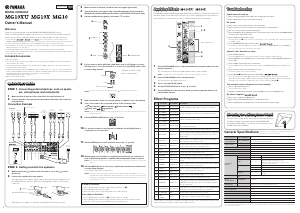
Quick Start GuideQuick Start Guide
STEP 1 Connecting external devices, such as speak-
ers, microphones and instruments
1
Make sure that all devices to be connected to the unit are turned off.
2 Connect speakers, microphones and instruments referring to the connection
example below.
Connection Example
Microphones
Electric acoustic guitar
Electric keyboard
Footswitch
(Yamaha FC5;
MG10XU/MG10X)
Powered
speaker
Headphones
Portable
audio player
R
R
Microphones
L
L
Powered
monitor speaker
R
R
L
L
L
L
R
R
L
R
Computer
Rear Panel
Top Panel
STEP 2 Getting sound to the speakers
1
Make sure that the [ /I] switch at the rear panel is set to the [ ] position
(power off).
2 Connect the supplied AC power adaptor.
1
Connect the power adaptor with the gap of the plug facing up, aligning it to the
[AC ADAPTOR IN] connector.
2
Turn the fastening ring clockwise to secure the
connection.
21
[AC ADAPTOR IN] jack
[
/I] switch
3
Plug the power adaptor securely into a standard household power outlet.
3 Make sure that all switches on the unit are not engaged (pressed in).
4 Turn all the level control knobs fully to the left (minimum). These include the
[GAIN] knobs (white), [LEVEL] knobs (white), and [STEREO LEVEL] knob (red).
5 Set the equalizer knobs (green) to the center “D” position.
5
Equalizer
4
LEVEL
4
GAIN
4
STEREO LEVEL
6 If you connect a device with high output level, such as a CD player or an elec-
tric keyboard, to one of the channels 1 to 4, turn on (O ) the [PAD] switch of the
corresponding channel*.
Channel
Channel number
PAD
*Channel: Location or path
where sound is input.
NOTE
If you are using condenser microphones, turn on (
O
) the [PHANTOM +48V] switch.
7 Make sure that the volume of a powered speaker or amplier is set to the minimum.
8 Turn on the power to the connected devices in the following order:
(microphone), (instrument), (audio device)
[
/I] (this unit) (speakers).
NOTICE
Follow this order to prevent any loud, unexpected noise from the speakers. Reverse the order when
turning the power off.
9 Set the [STEREO LEVEL] knob to the “L” position.
10 For channels to which a microphone is connected, set the [GAIN] knob to
roughly the 12 o’clock position.
11 Set the [LEVEL] knob of each channel in use to the “L” position.
12 While playing your instrument or speaking into the microphone, raise the vol-
ume of the powered speaker or amplier until the desired volume is reached.
NOTE
If the sound is not heard or the sound is distorted, follow the instructions in the boxed section below
step 13.
13 Set the [LEVEL] knobs as necessary to adjust the volume balance between the
corresponding channels.
This completes the STEP 2 instructions.
NOTE
The volume can be adjusted by using three functions; [PAD], [GAIN], and [LEVEL]. Once you set
the [PAD] switch and the [GAIN] knob, avoid adjusting those controls as much as possible. Instead
normally use the [LEVEL] knob to adjust the volume. For details about each function, see the “Con-
trols and Functions” section.


Praat mee over dit product
Laat hier weten wat jij vindt van de Yamaha MG10XU Mengpaneel. Als je een vraag hebt, lees dan eerst zorgvuldig de handleiding door. Een handleiding aanvragen kan via ons contactformulier.