
This product is designed to mount flat panel televisions weighing up to 75kg/165lbs to a vertical firm wall.
Safety Warning: Be careful to make sure there are no missing or defective parts. Never use defective parts. Improper
installation may cause damage or serious injury.
Note: The included hardware is for mounting on walls . If you are uncertain about the nature of your wall, consult an
expert. Please consult your hardware or installation professional for proper mounting to other types or walls. The
supplied hardware is not for steel.
Forbidden Instruction: Do not mount onto plasterboard or panelled walls.
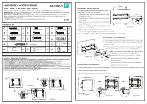
ASSEMBLY INSTRUCTIONS
FOR TILTING FLAT PANEL WALL MOUNT
1
2
3
Mounting the Wooden Wall Plate
Important! For safety, the mount must be secured to two
adjacent wood studs an least 40 cm apart.
1. Using a stud finder, locate and mark two adjacent studs
for securing the mount.
2. Place the wall plate against the wall and level it using the
bubble guide.
3. Make two locations (two per stud) on the wall where the
mount will be secured.
4. Remove the wall plate and drill a (4mm) pilot hole an each
location using an electric drill.
5. With the help of another person, replace the wall plate and fix
it to the wall using the Lag Bolts and Lag Bolt washers provided.
6. Do not over-tighten the bolts and do not release the wall plate until all screws are secure.
Mounting the Concrete Wall Plate
1. Place the wall plate against the wall and level it using the bubble guide.
2. With the help of another person, mark off four (4) locations for fixing the
mount to the wall.
3. Place the wall plate aside and drill a hole at each location using a 3/8"
(10mm) masonry bit. Remove any excess dust form the holes.
4. Insert one Concrete Anchor into each hole. A hammer can be
used to lightly tap the anchors into place if necessary.
5. With the help of another person, replace the wall plate
and fix it to the wall using the Lag Bolts and Lag Bolt
Washers provided.
6. Do not over-tighten the bolts and do not release the wall
plate until all screws are secure.
Final Installation and Adjustment
1. With the help of another person, carefully lift your display and place it on the wall plate. Do not release the display until the
mounting arms have securely hooked onto the mount.
2. Move the safty screws to the position as the picture shows .
Attaching the Arms to the Display
Important! Use extra care during this part of the installation. If possible, avoid placing your display face down as it may
damage the viewing surface. Note: Your mount comes with a selection of bolt diameters and lengths to accommodate a
wide variety of display models. Note all o f the hardware in the kit will be used.
1. Determine the correct length of bolt to use with your display by first examining the back of you display.
A. If your display has a flat back, you will use one of the shorter bolts from the hardware kit.
B. If your display has a curved or recessed back, you will use one of the longer bolts along with a spacer.
2. Determine the correct diameter of bolt to use by carefully trying one bolt each from the hardware kit. Do not force any
of the bolts-if you feel resistance stop immediately and by a smaller diameter bolt.
3. Attach the arms to the back of your display using the bolts identified along with corresponding washers.
A. If you are using the M4 or M5 bolts, you will also need to use the small hole of the washers n . If you are using the M6
or M8 boles, you will also need to use the big hole of the washers n .
B. If you are using one of the longer bolts on a display with a curved recessed back, you will also use a Spacer. Use the
Small Spacer for M4 and M5 bolts and the Large Spacer for M6 and M8 bolts.
4. Make sure all screws are secure, but do not over-tighten them.
5. Knobs should face the outside of the television
Hardware kit
Diagram-1
Diagram-2
Diagram-3
Diagram-6
Diagram-5
Diagram-4
Diagram-7 Diagram-8
40cm
o
k
j
k
o
SUPPLIED PARTS: Supplied joint parts are exclusive for using in this product. Other joint parts are forbidden to use on this product. If any parts are
missing or faulty, telephone the special franchiser for a placement.
M4x30mm Screw
x4
Big Spacer
x4
M5x30mm Screw
M6x30mm Screw
M8x25mm Screw
M8x40mm Screw
Concrete Anchor
6mm Lag Bolt
Small Spacer
Lag Bolt Washer
Washer
x4
x4
x4
x4
x4
a
b d
e
f
g
h i
x4
x4
x4
j
k l
x4
M4x12mm Screw
M5x12mm Screw
M6x12mm Screw
x4
x4
x4
m n
o
CI-26

Praat mee over dit product
Laat hier weten wat jij vindt van de Connect IT Cl-26 Muurbeugel. Als je een vraag hebt, lees dan eerst zorgvuldig de handleiding door. Een handleiding aanvragen kan via ons contactformulier.