Instructions manual
fig.4
OFF
fig.5
OK
150 cm
fig.8 fig.9
fig.7
Gewiss
“PLAYBUS”
“PLAYBUS YOUNG”
bticino
“LIVING
INTERNATIONAL”
-+
RESETE/IMODE PROG
-+
RESETE/IMODE PROG
fig.6
fig.1
Vimar
“IDEA”
“IDEA RONDO”
cod. 079470-02/10
fig.10
C
Auto
Man
Off
1 234567
fig.11
C
Auto
Man
Off
1 234567
fig.12
C
Auto
Man
Off
1 234567
fig.13
C
Auto
Man
Off
1 234567
fig.14
C
Auto
Man
Off
1 234567
fig.15
C
Auto
Man
Off
1234567
fig.16
C
Auto
Man
Off
1234567
fig.17
C
Auto
Man
Off
1234567
fig.18
C
Auto
Man
Off
1234567
fig.19
C
Auto
Man
Off
123456 7
fig.3
-+
RESETE/IMODE PROG
C
Auto
Man
Off
1 2 3 4 56 7
fig.2
-+
RESETE/IMODE PROG
C
Auto
Man
Off
1 2 3 4 56 7
G
CBA
D
E
F
M
N
L I H
INTRODUCTION
We would like to thank you for having confidence in our company and choosing our product.
This is an easy BUILT-IN ELECTRONIC PROGRAMMABLE THERMOSTAT with WEEKLY programming (which allows to create a specific program
for each day of the week). It allows an extremely accurate room temperature adjustment in the hosting room, thus meeting any user’s need
as far as room COMFORT is concerned.
The instructions below will permit simple and immediate use of the built-in programmable thermostat. Read them carefully and enjoy the comfort!
CONFORMITY TO THE STANDARDS CONFORMITY TO THE GUIDELINES
EN 60730-1 and subsequent revisions B.T. 73/23/CEE
EN 60730-2-7 EMC 89/336/CEE and later updating of 93/68/CEE
EN 60730-2-9
TECHNICAL DATA
POWER SUPPLY = 230V~/50Hz (+10% -15%)
TEMPERATURE RANGE = 6° C ¸ 38° C
MINIMUM PROGRAMMING TEMPERATURE = 0,1° C
ROOM TEMPERATURE ON DISPLAY = 0/40° C (accuracy 0,1° C)
TEMPERATURE ACQUISITION = at intervals of 1 min.
TEMPERATURE DIFFERENTIAL = 0,2 ÷ 0,4 K
SENSING ELEMENT = NTC 2%
DEGREE OF PROTECTION = IP 20 (on the installed appliance)
INSULATION CLASS =
TEMPERATURE RATE OF CHANGE = 1K/15 min.
OUTPUT = switching relay
CONTACTS RATING = 5(0,5)A/250V~
SWITCH ACTION = 1BU
INSTALLATION LOCATION = normal environment
MAXIMUM STANDING TEMPERATURE = 50° C
STORAGE TEMPERATURE = 0 ÷ 60° C
N°2 TEMPERATURE LEVELS which may be modified by the user
Pre-set temperatures: T1= 20°C - T2=16°C
ANTIFROST TEMPERATURE = fixed at 6° C
PROGRAMMING = weekly
N°1 PRE-SET PROGRAM WHICH MAY BE MODIFIED BY THE USER From Monday to Sunday and from 07:00 to 22:00
MINIMUM PROGRAMMING RANGE = 1 hour
OVERRIDE of the pre-set temperature (manual mode)
LCD DISPLAY
WINTER/SUMMER SWITCHING (heating/air-conditioning)
UNIT RESET
BACK-UP CHARGE = 200 hours (with Lithium buffer battery)
MOUNTING = in a 3-module standard built-in box
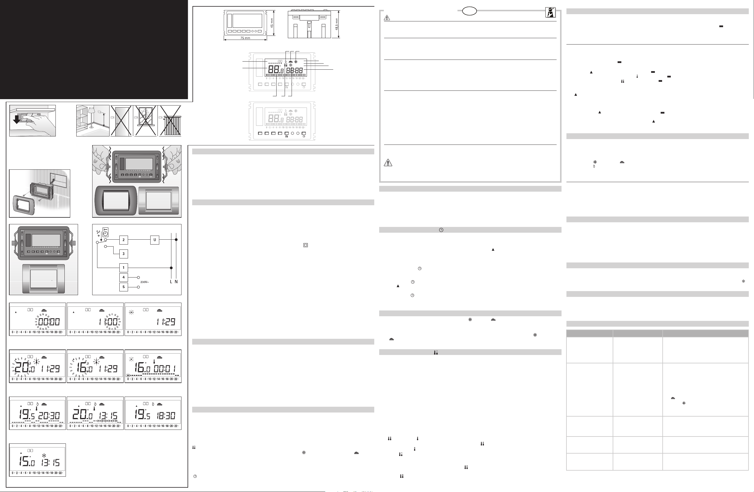
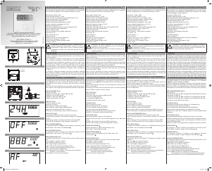
DISPLAY READINGS KEY (Fig.2)
A - System ON
B- Winter mode (heating system)
C- Summer mode (air-conditioning system)
D- AUTOMATIC mode
E- MANUAL mode
F- OFF mode (ANTIFROST function activated)
G- Display of current time
H- Antifrost mode
I- Temperature level “comfort” “reduced”
L- Time/temperature chart of the set program
M- Display of room temperature (fixed)/ requested temperature (blinking)
N- Days of the week
THERMOSTAT CONTROL KEYS (Fig.3)
– and + keys = Decrease and increase the set values and allow the user to move horizontally on the time/temperature chart during
programming.
MODE key = Allows selection of the desired mode : AUTO, MAN, OFF.
The activated mode appears on the display in a fixed manner. Each time the “MODE” key is pressed, the display proposes
one of the three available modes in sequence.
PROG key = Activates/ends the programming phase.
key = Allows to select one of the two temperature levels available (COMFORT or REDUCED)
E/I key = Allows to select between the SUMMER mode (air conditioning) “ ” and the WINTER mode (heating) “ ”.
RESET button = In case of thermostat operation anomalies, use the a pencil point to press the RESET button. When the RESET button is
pressed, neither the operating program settings nor the previously stored temperature levels are altered, but the thermostat
is prepared for time programming by reactivating the AUTO mode.
TIME SET
( ) key = Allows to set the time and day of the week.
INSTALLATION AND CONNECTIONS
SAFETY INSTRUCTIONS
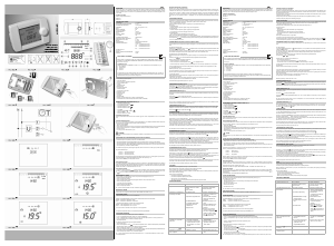
Before connecting the programmable thermostat, make sure that the electric power supply IS NOT SWITCHED ON and that its voltage
corresponds to the one mentioned on the appliance ( 230V~) (fig. 4)
PLACEMENT OF THE THERMOSTAT
Install the thermostat far from heat sources (radiators, direct sunlight and kitchens) and far from doors/windows, etc. To ensure its
correct operation, it is very important to place the thermostat at approx 1,5 m height above the floor and on interior walls; it is also
recommended to seal the conduit outlet of the boiler electrical wires. (fig. 5)
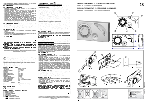
INSTALLATION
The thermostat unit is supplied completely assembled and already fitted in the suitable standard FRAME. Therefore the installation
is very simple and can be easily performed as follows:
Connect all the wires to the terminals as per the “wiring connections” paragraph below.
Insert the thermostat (with the relevant FRAME) in the 3-module standard built-in box, already fitted to the wall, and tighten it with
the screws provided. Fit the selected COVER PLATE in its correct position (fig.6)
PLATE POSITIONING
The particular design of the thermostat FRAME allows the fitting of different COVER PLATES, namely:
Bticino “LIVING INTERNATIONAL” plate
Gewiss “PLAYBUS” and “PLAYBUS YOUNG” plates
Vimar “IDEA” and “IDEA RONDÒ” plates
When fitting a “LIVING INTERNATIONAL” or “PLAYBUS”/”PLAYBUS YOUNG” plate, the side tabs on the FRAME should be broken off
and removed. (fig.7)
When fitting an “IDEA” or “IDEA RONDÒ” plate, the FRAME should not be modified and the side tabs should not be removed from
the FRAME. (fig.8)
NOTE: Two plastic strips are always provided with the device. When fitting Gewiss or Vimar plates, these strips may be used as
outside coverings to hide holes that may be visible on the front of the thermostat unit after its assembling.
WIRING CONNECTIONS
Connect the appliance power supply wires to terminals n° 4 and n° 5 located on the back side of the thermostat; the wires of the
UNIT TO BE CONTROLLED should be connected to terminals n° 1 and n° 2, as per the wiring diagram in fig.9.
U = unit to be controlled
1 = common contact
2 = normally-open contact
3 = normally-closed contact
4÷5 = power supply contacts
THERMOSTAT START-UP
When the appliance has been connected and the power supply has been switched on, all available segments and symbols will then be
displayed for a few seconds (AUTOTEST). The programmable thermostat is now ready for:
• CLOCK SETTING (time/day)
• TEMPERATURES SETTING
• AUTOMATIC MODE operating as per the preset program (if time/day setting have been configurated)
or
• OFF MODE (if time/day setting has not been configurated)
CLOCK SETTING (time/day)
This function is active in all three operating modes (AUTO, MAN, OFF).
Setting procedure
• Press once key “TIME SET”
The display shows the clock figures for HOURS (blinking), MINUTES and the symbol " " indicating the day of the week (at the beginning
it is pointing to MONDAY). (Fig.10).
• Press “–/+“ several times or continuously to set the HOUR (if pressed uninterruptedly the figures decrease/increase automatically and
gradually and stop blinking).
• Press once “TIME SET” ( ) to confirm the HOUR setting and to store it in the unit memory; the display will then show the MINUTES
figures (blinking). (Fig.11).
• Press “–/+“ several times or continuously to the MINUTES.
• Press “TIME SET” ( ) to confirm the MINUTES setting and to store it in the unit memory; the display will then show a blinking the
symbol “ ” indicating the day of the week. (Fig.12)
• Press “–/+“ several times or continuously to set the current DAY OF THE WEEK.
• Press “TIME SET” ( ) to confirm the DAY setting and to store it in the unit memory.
This concludes the CLOCK SETTING procedure and starts the operating TEMPERATURE SETTING procedure.
SUMMER/WINTER SETTING
The programmable thermostat can be programmed for “summer” ( ) or “winter” ( ) operation, depending on whether it is connected
to an air-conditioner or a boiler.
Setting procedure
• Use a pencil point to press the E/I key. Each time the key is pressed, the display will alternately show the symbol ( ) (air conditioning)
or ( ) (heating).
TEMPERATURE SETTING ( )
The programmable thermostat is provided with 2 TEMPERATURE LEVELS:
T
1
(
comfort
) = Ideal temperature when stay at home.
T
2
(
reduced
) = Temperature for night-time or periods during nobody stay at home (when the user is at work for several hours, etc.)
These temperature levels may be adjusted by the user and are factory pre-set and stored as follows:
T
1
= 20°C (COMFORT temperature)
T
2
= 16°C (REDUCED temperature)
If the above temperature levels need to be modified, it is very important to note that the lower temperature shall always be assigned to T
2
and the higher temperature to T
1
.
TEMPERATURE SETTING LIMITS
T
1
= starting from T2 up to 38° C
T
2
= starting from 6°C up to T1
Setting procedure
Press the MODE key to activate the AUTO mode.
The time, day of the week and activated mode (AUTO) are displayed.
Press key, the symbol “ ” and relative value set for this temperature T
1
will blink on the display.(Fig.13).
Press the keys – or + to decrease or increase the set value. Press the key “ ” , to store the value T
1
.
At this point the symbol “ ” and relative value set for this temperature T
2
will blink on the display.
Press the key “ ” to confirm the value of T
2
and exit the temperature setting procedure.
Press the keys – or + to decrease or increase the set value.
If, on the contrary, NO modifications are desired, press the key to confirm the pre-set temperature values for T
1
and T
2
(once to confirm T
1
and then again to confirm T
2
). (Fig.14).
Press the key “ ” , to store the value T
2
and to complete temperatures setting.
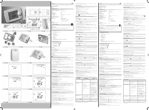
PROGRAM SETTING
A PRE-SET PROGRAM is stored in the unit memory (see the paragraph TECHNICAL DATA).
Make certain that the AUTO mode has been activated (see the Thermostat Control Keys paragraph).
During the PROGRAM SETTING procedure, the pre-set program chart will be displayed. This chart is composed of “ ” corresponding to
each programming period (1 hour), shown in the lower position if the reduced temperature is to be maintained during this period or in the
upper position if the comfort temperature is to be maintained during this period.
MODIFICATION OF THE PRE-SET PROGRAM
The example provided below is based on the factory pre-set program.
Setting procedure
During the 24h programming procedure, the clock does not indicate the current time but helps the user identify the start of the active period
indicated by the blinking the symbol " " .
• Press the PROG key to start the program modification procedure.
• The symbol “ ” pointing to Monday “1” and the symbol “ ” pointing to the “zero” hour (0) in the time/temperature chart will start
blinking. The display will also show the symbol “ ” since the symbol “ ” corresponding to the blinking time period is in the lower
position. (Fig.15). Each time the key “ ” is pressed, the symbol “ ” will alternate its position enabling the corresponding temperature
reference (low = reduced, high = comfort), shifting to the next hour to the right.
• If instead it is desired to set directly the programming of a specific day, press the PROG key repeatedly until the active day symbol
( ) blinks on the display.
• Press the –/+ keys to move HORIZONTALLY on the chart and set the next operating period.
• Follow the same procedure to program all 24 hours of the time/temperature chart.
• At the end of the chart definition regarding Monday “1”, press PROG to confirm the programming and move to the following day of the
week: the symbol “ ” pointing to Tuesday “2” and the symbol “ ” pointing to the “zero” hour (0) will now start blinking.
Set the time/temperature chart for Tuesday and the remaining days of the weeks following the same procedure.
• When the setting procedure is completed and the symbol “ ” is blinking pointing to Sunday “7”, press the PROG key to CONFIRM
and ACTIVATE the program just set.
AUTOMATIC MODE (AUTO)
NORMAL OPERATION CONDITIONS (Fig. 16)
During normal operation, the following are displayed:
4 The symbol of the set temperature presently ACTIVATED
4 The operating program chart with the relevant temperature level presently ACTIVATED (T
1
or T
2
)
4 the symbol ( ) or the symbol ( ) for summer or winter operation mode
4 the symbol ( ) indicating that the boiler or air-conditioner are operating
When the AUTOMATIC mode is selected, the programmable thermostat will manage the room temperature following the set program.
TEMPORARY MODIFICATION OF THE TEMPERATURE (Fig. 17)
With the AUTO mode activated, the temperature can be temporarily modified for a period of the program.
Press the – or + key once and the pre-set temperature T1 COMFORT to be maintained will blink on the display. Use the – and + keys to
set a new temperature value. If no key is pressed within about 8 seconds, the set value will be stored.
The segments corresponding to the part of the program that has been temporarily changed will blink on the display.
The programmable thermostat will return operating in AUTO mode at the next temperature change in the program. The temporary change
can be cancelled by pressing the MODE key.
MANUAL MODE
When the MAN mode is selected using the MODE key, the programmable thermostat will exclude the set program and operate as a simple
manual room thermostat, maintaining the room temperature at the set value during each hour of the day.
The pre-set temperature (20°C) to be continuously maintained will blink on the display (for about 8 seconds if it is not changed). A new
temperature value can be set using the – and + keys.
This value will continue to blink for another 8 seconds after which the display will resume showing the actual room temperature.
To display the value of the set temperature at any time, press the – and + key just once. Pressing the key again will change the value of
the temperature. To exit the MAN (manual) mode, press the MODE key and return to operation in AUTO mode.(Fig. 18)
OFF MODE (Fig. 19)
The OFF mode activates the ANTIFROST protection.
The programmable thermostat will manage the room temperature so that it does not fall below 6°C, thus protecting pipes from freezing during
long periods out of home. The display shows the actual room temperature, clock, activated mode (OFF) and the ANTIFROST symbol ( ).
USEFUL INFORMATION AND WARNINGS
f
When FIRST installing the unit, in case only the CLOCK SETTING procedure is carried out, the appliance will start normal operation,
activating the following operating conditions: T2=16° C; T1=20° C, PRE-SET PROGRAM (see TECHNICAL DATA), WINTERmode.
When first installing the unit, in case the CLOCK SETTING procedure is not completed in 10 minutes, the programmable thermostat
will automatically start the OVERRIDE MODE (OFF), assuring unit operation at the ANTIFROST temperature (factory pre-set at 6°C).
PROBLEM SOLVING
Note: If problems continue, do not tamper with any part of the product for any reason whatsoever, but contact Technical Service
WARNING:
It is recommended to install the programmable
thermostat strictly in compliance with all safety and
law provisions in force.
PROBLEM POSSIBLE CAUSE SOLUTION
The thermostat does
not turn on
1. Wrong wiring
2. False contact
1. Check the electric supply wiring
connections (230V~) to the thermostat
terminals n° 4 and n° 5
2. Press and keep pressed for 2-3 seconds the
RESET button
The thermostat does
not start/does not start
at the pre-set time
3. Wrong wiring
4. Wrong user program setting
5. Mode other than AUTO
activated
6. Wrong summer/winter
setting
7. Wrong current time/day
of the week setting
3. Check the wiring connections of the UNIT TO BE
CONTROLLED to the thermostat terminals n° 1 and n° 2
4. Check Time/Temperature chart settings on display
to verify their correctness
5. Activate the AUTO mode
6. Make sure that the display shows the symbol
( ), if the appliance is connected to a boiler or the
symbol ( ), if connected to an air-conditioner.
7. Check current time and day of the week and,
if wrong, reset them.
The display temperature does
not correspond to the actual
temperature
8. Incorrect positioning of the
thermostat within the room
9. Air-draught coming from the
electrical wire conduit
8./9. Follow the instructions of the paragraph
“Placement of the thermostat”.
After pressing the RESET button,
the display does
not light up
10.RESET button got stuck
under the plastic
10.Release the button using a pencil point,
so that it goes back to its proper position
The reading “batt” is
displayed
11.Lack of power supply voltage
(230V~)
11.Switch on the electrical power supply and eventually
press the RESET button and perform again the time
setting procedure.
IMP_503N cod 79470_Layout 3 18/02/10 11:04 Pagina 2


Praat mee over dit product
Laat hier weten wat jij vindt van de IMIT CRD/503N Thermostaat. Als je een vraag hebt, lees dan eerst zorgvuldig de handleiding door. Een handleiding aanvragen kan via ons contactformulier.