
AQ . B . 14 - 51 . 10 . AK Code No. 11551-8915-6
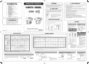
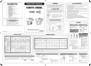
Thank you very much for purchasing a KUBOTA diesel engine. We believe
that it will serve you without fail. Before use, be sure to read this Operator’s
Manual carefully. With proper handling and maintenance, this diesel engine
will provide excellent service over an extended period of time.
This symbol, the industry's “Safety Alert Symbol”, is used throughout this
manual and on labels on the machine itself to warn of the possibility of
personal injury. Read these instructions carefully. It is essential that you
read the instructions and safety regulations before you attempt to assemble
or use this unit.
When you want to have servicing from the dealer from whom you purchased
your KUBOTA diesel engine, please inform them of the model number and
serial number of your KUBOTA diesel engine.
1. Before operation, wear a proper cap and work clothes to prevent clothing, hair, towels and such
from getting caught in the engine.
2. Before operation, check all set bolts and nuts for looseness and tighten if necessary.
3. Avoid placing inflammable materials close to the engine during operation.
4. As exhaust gases are harmful:
(1) Avoid operating the engine in an ill-ventilated place or where exhaust gases accumulate easily.
(2) Take special care during operation to prevent exhaust gases from affecting yourself, or people
or animals around you.
5. When using an belt, install a cover, fence or similar device to prevent the risk of injury. Be sure to
stop the engine before installing or removing the belt.
6. If the engine is to be lent to somebody, explain the handling procedures and point out that the
Operator’s Manual must be read carefully before use.
7. Keep children away from the engine during operation.
8. Do not touch the muffler, exhaust pipe or other hot parts during or immediately after operation.
9. Always stop the engine in the following cases:
(1) When checking, adjusting or cleaning each part
(2) When discharging, pouring or injecting oil from or into each part
(3) When cleaning off dust or other foreign matter accumulated on the muffler
10.Do not use or charge the battery if its fluid level stands below the LOWER mark.
Otherwise, the component parts may deteriorate earlier than expected, which may shorten the
service life or cause an explosion. Immediately, add distilled water until the fluid level is between
the UPPER and LOWER levels.
PULLEY
To achieve the most efficiency, the pulley must be a size most appropriate
for the machine to be driven by the engine. If the size of the pulley is not
suited to the machine, the engine will emit black fumes and output will
decrease, not only lowering operating efficiency, but also reducing the
life of the engine.
To select the proper pulley size, use the following formula:
3Engine pulley size:
Machine
pulley size
Machine speed
Engine speed
3Machine pulley size:
Engine
pulley size
Engine speed
Machine speed
WIRING DIAGRAM GENUINE REGULATOR INSTALLATION EXAMPLE HOW TO HOIST UP THE ENGINE
[NOTE]
3 This engine hook cannot be used to
hoist up the engine with a machine.
BATTERY
Battery and battery cable are not
equipped with the engine.
Please buy them usually sold in shop.
Recommended capacity of battery
(5hr Ratio)
AC60, OC60
2832Ah
OC80, OC95
3648Ah
INSPECTION
Always handle the battery correctly to
ensure maximum performance.
(1) Always carry out daily inspection and
maintenance, and charge the battery
before the voltage drops.
(2) Allowing the fluid level to get too low
will damage the battery. Add distilled
water as necessary.
CONNECTING
Connect
thick cable
to plus () terminal of battery
ground cable to minus () terminal of battery
CAUTION
3
3 Do not spoil clothes and skin
with battery electolyte.
As the battery electolyte is
dilute sulfuric acid, it will
damage the clothes. Wash
away when battery electrolyte
sticks to the clothes.
CHARGING
DANGER
3
3 Do not use or charge the
battery if its fluid level stands
below the LOWER (lower limit
level) mark.
Otherwise, the battery
component parts may
deteriorate earlier than
expected, which may shorten
the battery’s service life or
cause an explosion.
Immediately, add distilled
water until the battery’s fluid
level is between the UPPER
and LOWER levels.
Some of the engine parts–e.g., fuel filter
–are not resistant to acids. Be sure to
charge the battery in a place away from
the engine, following the instructions of
the battery manufacturer.
Engine serial number
Engine model number (AC type)
Engine model number (OC type)
Installing the regulator Grounding the regulator
3
DANGER : Indicates an imminently hazardous situation which, if
not avoided, will result in death or serious injury.
3
CAUTION: Indicates a potentially hazardous situation which, if
not avoided, MAY result in minor or moderate injury.
IMPORTANT : Indicates that equipment or property damage could
result if instructions are not followed.
NOTE : Gives helpful information.
[NOTE]
3 This WIRING DIAGRAM is for the
standard model (with 48W generator).
This is different from that of the model
with 180W generator in wiring for the
regulator.
California Proposition 65
3 WARNING 3
The engine exhaust from this product
contains chemicals known to the State
of California to cause cancer, birth
defects or other reproductive harm.
PRINTED IN JAPAN
© KUBOTA Corporation 1989
Crankcase oil
Daily
25 hours after
initial operation
Every 100 hours
@
@
@
Every 300 hours Every 500 hours Every 800 hours
Every 1500 hours Every 3000 hours
Every 1 year Every 2 year
Position
Interval
Air cleaner
(paper element type)
Fuel filter
Fuel tank
Tail pipe of muffler
Rubber hoses and
Clamp bands
Valve clearance
Nozzle
Injection pump
Battery
Consult your local KUBOTA Dealer for this service.
3 When the battery is used for less than 100 hours in a year, check its electrolyte yearly. (for refillable battery’s only)
3 The items listed above (@ marked) are registered as emission related critical parts by KUBOTA in the U.S. EPA nonroad emission regulation. As the engine
owner, you are responsible for the performance of the required maintenance on the engine according to the above instruction.
Please see the Warranty Statement in detail.
Check Replenishment Cleaning Changing
[NOTE]
3 The item marked with should be carried out when the work site is especially dusty.
3 Some models have no tail pipe.
PERIODIC SERVICE
SPECIFICATIONS
Type
Vertical, air-cooled, 4-cycle diesel engine
Vertical, Oil & Air-cooled, 4-cycle diesel engine
1Number of cylinders
Bore Stroke (mm) 7268 7777 8377
0.276 0.358 0.416Displacement (L)
Rated output (kW/rpm) 4.1/3600 4.1/1800 4.1/3600 4.1/1800 5.1/3600 5.1/1800 6.3/3600 6.3/1800
4.6/3600 4.6/1800 4.5/3600 4.5/1800 5.9/3600
379.5 331 426
462 409 500
429 434 478
––– 38 56
32 35 –––
36 39 –––
5.9/1800 7.0/3600 7.0/1800
Maximum output (kW/rpm)
Dimensions
Weight (kg)
Length (mm)
Width (mm)
Height (mm)
Electric start
Recoil start
Electric & recoil
Cooling system Air-cooled ACTV (Oil & Air cooling)
Combustion system
Direct injection system
TVCS (swirl chamber type)
Fuel Diesel fuel oil (SAE No.2-D)
API Service CF, CD or CE-class (SAE #30, 20, 10W30)
Forced lubrication with trochoid pump
3.6 5.5
1.3 1.7
Counterclockwise viewed from the power take-off shaft
12V, 0.7kW starting motor/ Recoil starter 12V, 1.2kW starting motor
Lubricating oil
Lubricating system
Fuel tank capacity (L)
Crankcase oil capacity (L)
Rotational direction
Starting system
3 Specifications are subject to change for improvement without prior notice.
Specifications
AC60-D AC60-G OC60-D OC60-G OC80-D OC80-G OC95-D OC95-G
Model
FOREWORD
3
SAFETY FIRST
REQUESTING SERVICING



Praat mee over dit product
Laat hier weten wat jij vindt van de Kubota OC60 Aandrijfmotor. Als je een vraag hebt, lees dan eerst zorgvuldig de handleiding door. Een handleiding aanvragen kan via ons contactformulier.