7
1. Select a Location
When choosing a location for your timer, consider the
following:
• Choose location near a power source (if hard wiring) or
electrical outlet (applicable only to U.S. retail timers)
• Ensure operating temperatures are not below 32° or
above 158° Fahrenheit (below 0° Celsius or above 70°
Celsius)
• Place it away from direct sunlight if possible
• Ensure at least 9” of space to the left of the sprinkler
timer box for the door to swing open after installation
• Locate the timer where there is easy access to sprinkler
wire (from valves). If mounted in an outdoor location,
shut the compartment door to keep the timer safe
from weather damage. To lock: insert the key and turn
clockwise to the locked position
Note: Sprinkler timers are weather-resistant to UL-50 and ETL
®
Listings, but should not be placed in areas where continuous
water could cause damage.
2. Mount the Timer
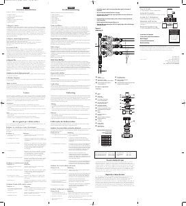
• Use the mounting template (included) to mark the
mounting screw location on the wall. See figure 1
• Install a No. 8 screw (included) into wall in the upper
template location. Leave the screw head protruding 1/8”
(3mm) from wall. Use expanding anchors (included) in
plaster or masonry, if necessary, for a secure hold
• Slip the timer over protruding screw (using keyhole slot
in back of timer). See figure 2
• Drive a No. 8 screw through one of the two pre-formed
holes located in lower back cabinet. See figure 2
3. Connect Valve Wires to Timer
• Strip 1/2” (12 mm) of the plastic insulation off the end of
each wire for both the timer wires and the valve wires
• Connect one wire from each valve (it doesn’t matter
which wire) to a single “Common” sprinkler wire (usually
white)
• Connect the remaining wire from each valve to a
separate colored sprinkler wire
See figure 3
Note: The maximum loading for each station/pump is 250mA,
the maximum loading for the timer is 500mA.
If the distance between the sprinkler timer and valves is under
700’ (210 m), use Orbit
®
sprinkler wire or 20 gauge (AWG) plastic
jacketed thermostat wire to connect the sprinkler timer to the
valves. If the distance is over 700’ (210 m), use 16 gauge (AWG) wire.
Important: All wires should be joined together using wire nuts,
solder, and/or vinyl tape. In wet environments like a valve box it
is recommended to use Orbit Grease Caps to prevent corrosion of
the connection and for protection from water infiltration.
Wiring Electric Valves
Strip 1/2” (12 mm) of plastic insulation off the end of each
individual wire. Each valve has two wires. One wire (it doesn’t
matter which one) is to be connected as the common. The
Figure 2: Hang timer on screw using keyhole
Figure 3:
Wiring Electric Valves
other valve wire is to be connected to the specific station wire
that will control that valve. The common wires for all the
valves can be connected together to one common wire going
to the controller. To avoid electrical hazards, only one valve
should be connected to each station. See figure 4
Important: The wire can be buried in the ground; however, for more
protection wires can be pulled through PVC pipe and buried under-
ground. Be careful to avoid burying the wires in locations where
they could bedamaged by digging or trenching in the future.
Your timer is equipped with the simple “push-in” terminals for
easy connection. Connect common wire to the common terminal.
Connect remaining wires to corresponding terminal locations.
ENGLISH



Praat mee over dit product
Laat hier weten wat jij vindt van de Orbit 91894 Besproeiingscomputer. Als je een vraag hebt, lees dan eerst zorgvuldig de handleiding door. Een handleiding aanvragen kan via ons contactformulier.