- 9 -
- 10 -
- 11 -
- 12 - - 13 - - 14 -
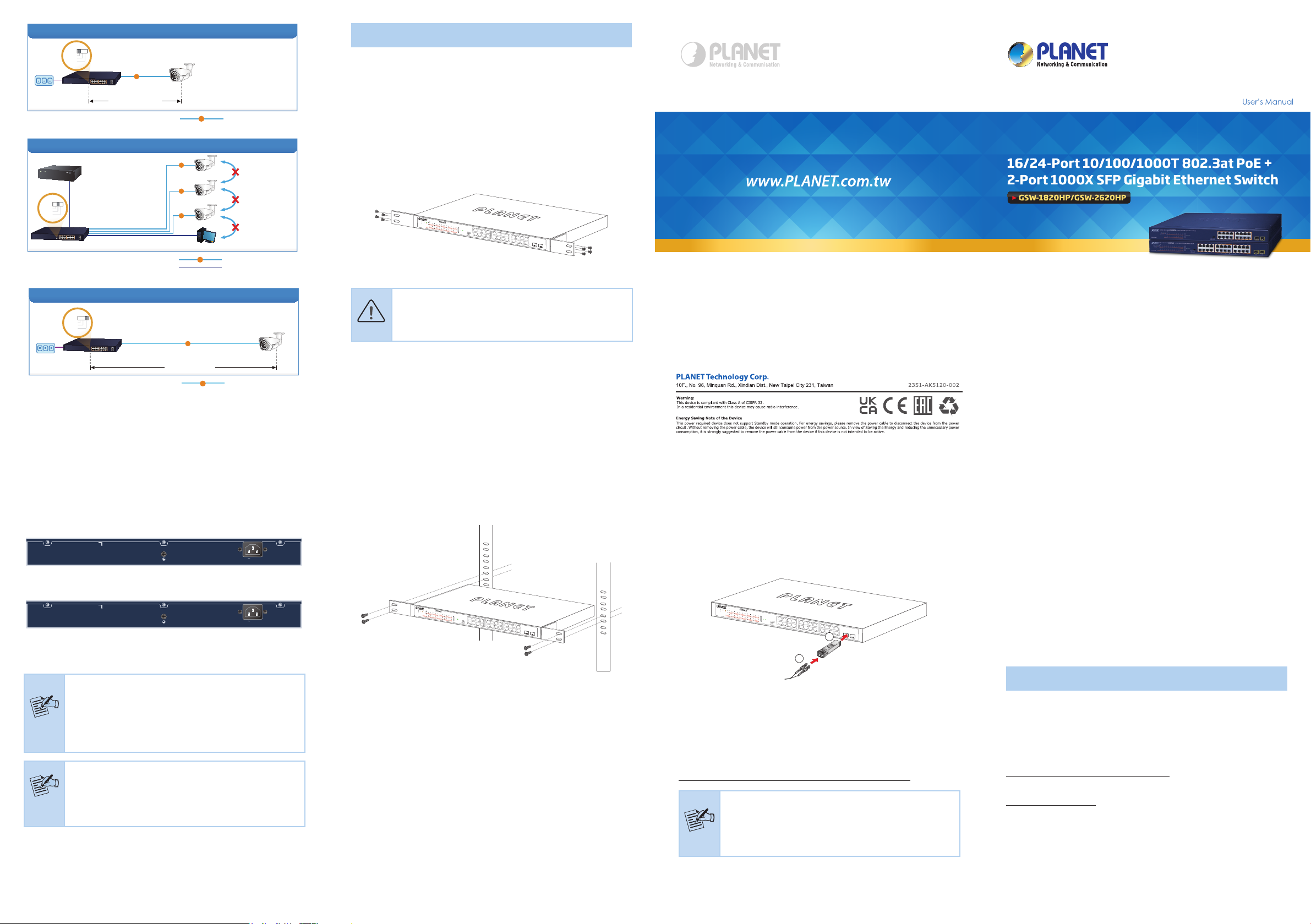
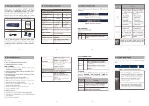
Standard Mode (default)
Power
PoE IP Camera
PoE
100 meters (328 feet)
PoE
100BASE-TX UTP with PoE
GSW-1820HP
Standard
VLAN
Extend
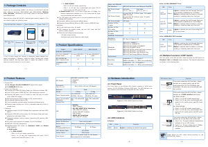
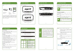
VLAN Isolation Mode
NVR
PC
Ports 1 to 14
Access Denied
PoE
PoE
PoE
PoE
100BASE-TX UTP with PoE
GSW-1820HP
IP Camera
IP Camera
IP Camera
Ports 15~16 and SFP Ports 17~18
to Ports 1~14 Access Permitted
Standard
VLAN
Extend
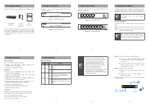
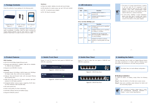
Extend Mode
Ports 1 to 8
Power
250 meters (820 feet)
PoE
PoE
10BASE-T UTP with PoE
PoE IP Camera
GSW-1820HP
Standard
VLAN
Extend
5. Hardware Installation
5.1 Rack Mounting
To install the 802.3at PoE+ Switch in a 19-inch standard rack, follow the
instructions described below.
Step 1: Place your 802.3at PoE+ Switch on a hard at surface, with
the front panel positioned towards your front side.
Step 2: Attach a rack-mount bracket to each side of the 802.3at PoE+
Switch with supplied screws attached to the package. Figure
5-1 shows how to attach brackets to one side of the 802.3at
PoE+ Switch.
GSW-2824P
PWR
1
2
3
4
1 2 3 4 5 6 7 8 9 10 11 12 13 14 15 16 17 18 19 20 21 22 23 24
5
6
7
8
9
10
11
12
13
14
15
16
17
18
19
20
21
22
23
24
25
26
27
28
1 2
3 4
5 6
7 8
9 10
11 12
13 14
15 16
17 18
19 20
21 22
23 24
26
25
28
27
27
28
Standard
VLAN
Extend
24-Port 10/100/1000T 802.3at PoE
+
2-Port 10/100/1000T
+
2-Port Gigabit TP/SFP Combo Ethernet Switch
10/100
1000
LNK/ACT
LNK/ACT
PoE-in-Use
1000X SFP
1 3 5 7 9 11 13 15 17 19 21 23
2
PWR
4 6 8 10 12 14 16 18 20 22 24
25
26
GSW-2620HP
PoE-in-Use
ACTLNK1000
ACTLNK10/100
PoE-in-Use
ACTLNK1000
Standard
Extend
VLAN
25
18 20 22 24
17 19 21 23
10 12 14 16
9 11 13 15
2 4 6 8
1 3 5 7
26
24-Port 10/100/1000T
802.3at PoE
+
2-Port 1000X SFP Gigabit Ethernet Switch
Figure 5-1: Attaching the Brackets to the 802.3at PoE+ Switch.
Caution
You must use the screws supplied with the mounting
brackets. Damage caused to the parts by using incorrect
screws would invalidate the warranty.
Step 3: Secure the brackets tightly.
Step 4: Follow the same steps to attach the second bracket to the
opposite side.
4.4 Rear Panel
The rear panel of the 802.3at PoE+ Switch indicates an AC power
socket, which accepts input power from 100 to 240V AC, 50-60Hz, 3A.
100-240V , 50/60Hz, 3A max.
Figure 4-3: GSW-1820HP Switch Rear Panel
100-240V , 50/60Hz, 3A max.
Figure 4-4: GSW-2620HP Switch Rear Panel
AC Power Receptacle
Power
Notice
The device is a power-required device, which means
it will not work till it is powered. If your networks
should be active all the time, please consider using UPS
(Uninterrupted Power Supply) for your device. It will
prevent you from network data loss or network downtime.
Power
Notice
In some areas, installing a surge suppression device may
also help to protect your 802.3at PoE+ Switch from being
damaged by unregulated surge or current to the 802.3at
PoE+ Switch or the power adapter.
Step 5: After the brackets are attached to the 802.3at PoE+ Switch,
use suitable screws to securely attach the brackets to the
rack, as shown in Figure 5-2.
GSW-2824P
PWR
1
2
3
4
1 2 3 4 5 6 7 8 9 10 11 12 13 14 15 16 17 18 19 20 21 22 23 24
5
6
7
8
9
10
11
12
13
14
15
16
17
18
19
20
21
22
23
24
25
26
27
28
1 2
3 4
5 6
7 8
9 10
11 12
13 14
15 16
17 18
19 20
21 22
23 24
26
25
28
27
27
28
Standard
VLAN
Extend
24-Port 10/100/1000T 802.3at PoE
+
2-Port 10/100/1000T
+
2-Port Gigabit TP/SFP Combo Ethernet Switch
10/100
1000
LNK/ACT
LNK/ACT
PoE-in-Use
1000X SFP
1 3 5 7 9 11 13 15 17 19 21 23
2
PWR
4 6 8 10 12 14 16 18 20 22 24
25
26
GSW-2620HP
PoE-in-Use
ACTLNK1000
ACTLNK10/100
PoE-in-Use
ACTLNK1000
Standard
Extend
VLAN
25
18 20 22 24
17 19 21 23
10 12 14 16
9 11 13 15
2 4 6 8
1 3 5 7
26
24-Port 10/100/1000T
802.3at PoE
+
2-Port 1000X SFP Gigabit Ethernet Switch
Figure 5-2: Mounting the 802.3at PoE+ Switch in a Rack
Step 6: Connect your 802.3at PoE+ Switch to 802.3af/802.3at
complied PDs and other network devices.
A. Connect one end of a standard network cable to the
10/100/1000BASE-T RJ45 ports on the front panel of the 802.3at
PoE+ Switch.
B. Connect the other end of the cable to the network devices such as
printer servers, workstations or routers, etc.
Step 7: Supply power to the 802.3at PoE+ Switch.
A. Connect one end of the power cable to the 802.3at PoE+ Switch.
B. Connect the power plug of the power cable to a standard wall
outlet.
When the 802.3at PoE+ Switch receives power, the power LED should
remain solid Green.
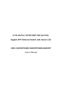
5.2 Installing the SFP Transceiver
The sections describe how to insert an SFP transceiver into an SFP slot
of the 802.3at PoE+ Switch.
The SFP transceivers are hot-pluggable and hot-swappable. You can plug
in and out the transceiver to/from any SFP port without having to power
down the 802.3at PoE+ Switch, as Figure 5-3 shows.
1 3 5 7 9 11 13 15 17 19 21 23
2
PWR
4 6 8 10 12 14 16 18 20 22 24
25
26
GSW-2620HP
PoE-in-Us e
ACTLNK1000
ACTLNK10/100
PoE-in-Use
ACTLNK1000
Standard
Extend
VLAN
25
18 20 22 24
17 19 21 23
10 12 14 16
9 11 13 15
2 4 6 8
1 3 5 7
26
24-Port 10/100/1000T
802.3at PoE
+
2-Port 1000X SFP Gigabit Ethernet Switch
MGB-Series
SFP Transceiver
LC Fiber Cable
1
2
Figure 5-3: Plug In the SFP Transceiver
Approved PLANET SFP Transceivers
PLANET 802.3at PoE+ Switch supports both single mode and multi-
mode SFP transceivers. The website link of approved PLANET SFP
transceivers is shown below:
http://www.planet.com.tw/en/product/product.php?id=11027
Note
It is recommended to use PLANET SFP on the 802.3at
PoE+ Switch. If you insert an SFP transceiver that is not
supported, the 802.3at PoE+ Switch will not recognize it.
1. Before we connect the 802.3at PoE+ Switch to the other network
device, we have to make sure both sides of the SFP transceivers are
with the same media type, for example, 1000BASE-SX to 1000BASE-
SX; 1000BASE-LX to 1000BASE-LX.
2. Check whether the ber-optic cable type matches with the SFP trans-
ceiver requirement.
To connect to 1000BASE-SX SFP transceiver, please use the
multi-mode ber cable with one side being the male duplex LC
connector type.
To connect to 1000BASE-LX SFP transceiver, please use the
single-mode ber cable with one side being the male duplex LC
connector type.
Customer Support
Thank you for purchasing PLANET products. You can browse our online
FAQ resource on PLANET Web site rst to check if it could solve your
issue. If you need more support information, please contact PLANET
support team.
PLANET online FAQs:
https://www.planet.com.tw/en/support/faq
Support team mail address
Copyright © PLANET Technology Corp. 2022
Contents are subject to revision without prior notice.
PLANET is a registered trademark of PLANET Technology Corp.
All other trademarks belong to their respective owners.


Praat mee over dit product
Laat hier weten wat jij vindt van de Planet GSW-1820HP Switch. Als je een vraag hebt, lees dan eerst zorgvuldig de handleiding door. Een handleiding aanvragen kan via ons contactformulier.