
2005 Sony Corporation Printed in Korea
XM-D6000GTX
MONAURAL
Power Amplifier
Amplificador
Operating Instructions
Manual de instrucciones
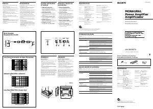
Features
•Maximum power output of 1,400 W (at 2 Ω).
•Class D Technology*
•This Power Amplifier is designed to be used
with subwoofers only.
•Direct connection can be made with the speaker
output of your car audio unit if it is not
equipped with a line output (High level input
connection).
•Built in variable LPF (Low-pass filter),
subsonicfilter (OFF/ON, 15 Hz), and low boost
circuit.
•Protection circuit and indicator provided.
•Two speakers terminals for parallel subwoofer
connections.
* Class D Technology
The Class D Technology is a method to convert and
amplify music signals with MOSFETs to high speed
pulse signals.
Furthermore, it features high efficiency and low
heat generation.
POWER/PROTECTOR
LEVEL
0+10dB
LPF
50
300Hz
6
2
4
0.3V
0.5
70
100
LOW BOOST
(40Hz)
SUBSONIC
FILTER
OFF
ON
2-541-807-21 (1)
Specifications
Circuit system Class D Technology
Pulse power supply
Inputs RCA pin jacks
High level input connector
Outputs Speaker terminals
Through out pin jacks
Suitable speaker impedance
2 – 8 Ω
Maximum outputs
800 W (at 4 Ω)
1,400 W (at 2 Ω)
Rated outputs (supply voltage at 14.4 V)
300 W RMS (20 Hz – 200 Hz, 1.0
% THD + N, at 4 Ω)
600 W RMS (20 Hz – 200 Hz, 1.0
% THD + N, at 2 Ω)
SN Ratio 76 dBA (Reference 1W into 4Ω)
Frequency response
5 – 300 Hz ( dB)
Harmonic distortion
0.04 % or less (at 100 Hz, 4 Ω)
Input level adjustment range
0.3 – 6.0 V (RCA pin jacks)
6.5 – 16.0 V (High level input)
Sub-sonic filter 15 Hz, – 12 dB/oct
Low-pass filter 50 – 300 Hz, – 12 dB/oct
Low boost 0 – 10 dB (40 Hz)
Power requirements
12 V DC car battery
(negative ground)
Power supply voltage
10.5 – 16 V
Current drain at rated output: 75 A (at 2 Ω)
Remote input: 2 mA
Dimensions Approx. 400 × 55 × 276 mm
(w/h/d) not incl. projecting
parts and controls
Mass Approx. 4.6 kg not incl.
accessories
Supplied accessories
Mounting screws (4)
High level input cord (1)
Protection cap (1)
Design and specifications are subject to change
without notice.
Installation
Before Installation
•Mount the unit either inside the trunk or under
a seat.
•Choose the mounting location carefully so the
unit will not interfere with the normal
movements of the driver and it will not be
exposed to direct sunlight or hot air from the
heater.
•Do not install the unit under the floor carpet,
where the heat dissipation from the unit will be
considerably impaired.
First, place the unit where you plan to install it,
and mark the positions of the four screw holes on
the surface of the mounting board (not supplied).
Then drill the holes approximately 3 mm in
diameter and mount the unit onto the board with
the supplied mounting screws. The supplied
mounting screws are 15 mm long. Therefore,
make sure that the mounting board is thicker
than 15 mm.
Parts for Installation and Connections
Componentes de instalación y conexiones
1
2
(× 4)
3
0.2 m
ø 5 × 15 mm
Troubleshooting Guide
The following checklist will assist in the correction of most problems which you may encounter with
your unit.
Before going through the checklist below, refer to the connection and operating procedures.
Problem
The POWER/PROTECTOR
indicator does not light up.
The POWER/PROTECTOR indicator
will change from green to red.
• The unit becomes abnormally
hot.
• The sound is interrupted.
Alternator noise is heard.
The sound is too low.
Cause/Solution
The fuse is blown. t Replace all fuses with a new one.
The ground wire is not securely connected.
t Fasten the ground wire securely to a metal point of the car.
The voltage going into the remote terminal is too low.
• The connected car audio unit is not turned on. t Turn on the car audio unit.
• The system employs too many amplifiers. t Use a relay.
Check the battery voltage (10.5 – 16 V).
Turn off the power switch. The speaker outputs are shorted.
t Rectify the cause of the short.
Turn off the power switch. Make sure the speaker cord and ground wire are
securely connected.
The unit heats up abnormally.
• Use speakers with suitable impedance. t2 – 8 Ω.
• Make sure to place the unit in a well ventilated location.
The thermal protector is activated. t Reduce the volume.
The power connecting wires are installed too close to the RCA pin cords.
t Keep the power connecting wires away from the RCA pin cords.
The ground wire is not securely connected.
t Fasten the ground wire securely to a metal point of the car.
Negative speaker cords are touching the car chassis.
t Keep the cords away from the car chassis.
The LEVEL adjustment control is not appropriate. Turn the LEVEL adjustment
control in the clockwise direction.
Buffer
AMP
Power
Lch
INPUT
THROUGH
OUT
Rch
Lch
Rch
LOW BOOST
LPF
SUBSONIC FILTER
ON
OFF
LEVEL
10
0
510 40 100
300
10
0
-10
-20
-30
-40
-50
-60
10 100 1k 2
50Hz
LOW PASS
100Hz
300Hz
dB
dB
Hz
Low boost/Incremento de bajas frecuencias
Low Pass Filter/Filtro de paso bajo
Frequency/Frecuencia
Block Diagram
Diagrama del circuito
Unit : mm
Unidad: mm
237
276
55
400
6
1
370
HzFrequency/Frecuencia
Subsonic Filter/Filtro subsónico
12.0
0
-30.0
510 100
OFF
ON (15 Hz)
HzFrequency/Frecuencia
dB
Location and Function
of Controls
1 POWER/PROTECTOR indicator
Lights up in green during operation.
When the PROTECTOR is activated the
indicator will change from green to red.
When the PROTECTOR is activated refer to
the TroubleShooting Guide.
2 LEVEL adjustment control
The input level can be adjusted with this
control. Turn it in the clockwise direction
when the output level of the car audio unit
seems low.
3 Cut-off frequency adjustment control
Sets the cut-off frequency (50 – 300 Hz) for
the low-pass filters.
4 SUBSONIC FILTER switch
When the SUBSONIC FILTER switch is set to
ON, the subsonicfilter (15 Hz) is effective.
5 LOW BOOST level control
Turn this control to boost the frequencies
around 40 Hz to a maximum of 10 dB.
Especificaciones
Sistema de circuito
Tecnología de clase D
Suministro de alimentación por
impulsos
Entradas Tomas de pines RCA
Conector de entrada de alto nivel
Salidas Terminales de altavoz
Tomas de pines THROUGH OUT
Impedancia adecuada del altavoz
2 – 8 Ω
Salidas máximas 800 W (a 4 Ω)
1 400 W (a 2 Ω)
Salidas nominales (tensión de suministro a 14,4 V)
300 W RMS (20 – 200 Hz,
1,0% THD + N, a 4 Ω)
600 W RMS (20 – 200 Hz,
1,0% THD + N, a 2 Ω)
Relación SN 76 dBA (referencia de 1W en 4Ω)
Respuesta de frecuencia
5 – 300 Hz (
dB)
Distorsión armónica
0,04% o inferior (a 100 Hz, 4 Ω)
Margen de ajuste de nivel de entrada
0,3 – 6 V
(Tomas de pines RCA)
6,5 – 16 V
(Entrada de alto nivel)
Filtro subsónico 15 Hz, – 12 dB/oct
Filtro de paso bajo
50 – 300 Hz, –12 dB/oct
Incremento de bajas frecuencias
0 – 10 dB (40 Hz)
Requisitos de alimentación
Batería de automóvil de cc de
12 V (negativo a masa)
Tensión de suministro de alimentación
10,5 – 16 V
Consumo de energía
Con salida nominal: 75 A (a 2 Ω)
Entrada remota: 2 mA
Dimensiones Aprox. 400 × 55 × 276 mm
(an/al/prf) sin incluir partes ni
controles salientes
Peso Aprox. 4,6 kg accesorios excluidos
Accesorios suministrados
Tornillos de montaje (4)
Cable de entrada de alto nivel (1)
Cubierta protectora (1)
Diseño y especificaciones sujetos a cambios sin
previo aviso.
Ubicación y función de
los controles
1 Indicador POWER/PROTECTOR
Se ilumina en verde durante el uso.
Si se activa PROTECTOR, el indicador
cambiará de verde a rojo.
Si se activa PROTECTOR, consulte la guía de
solución de problemas.
2 Control de ajuste LEVEL
Mediante este control se puede ajustar el
nivel de entrada. Gírelo en el sentido de las
agujas del reloj si el nivel de salida del
sistema de audio para automóvil parece bajo.
3 Control de ajuste de la frecuencia de corte
Ajusta la frecuencia de corte (50 – 300 Hz)
para los filtros de paso bajo.
4 Interruptor SUBSONIC FILTER
Cuando el interruptor SUBSONIC FILTER
está ajustado en ON, se activa el filtro
subsónico (15 Hz).
5 Control de nivel LOW BOOST
Gire este control para incrementar las
frecuencias alrededor de 40 Hz hasta un
valor máximo de 10 dB.
Instalación
Antes de realizar la instalación
•Monte la unidad en el interior del maletero o
debajo de un asiento.
•Elija cuidadosamente el lugar de instalación de
forma que la unidad no dificulte los
movimientos normales del conductor y no
quede expuesta a la luz solar directa ni al aire
caliente de la calefacción.
•No instale la unidad debajo de la moqueta del
suelo, en cuyo caso la disipación de calor de la
misma disminuirá considerablemente.
En primer lugar, coloque la unidad donde tenga
previsto instalarla y marque sobre la superficie
del tablero de montaje (no suministrado) las
posiciones de los cuatro orificios para los
tornillos. A continuación, perfore los orificios con
un diámetro de aproximadamente 3 mm y monte
la unidad sobre el tablero con los tornillos de
montaje suministrados. Compruebe que el grosor
del tablero de montaje sea superior a 15 mm, ya
que la longitud de estos tornillos es de 15 mm.
Características
•Salida máxima de potencia de 1 400 W (a 2 Ω).
•Tecnología de clase D*
•Este amplificador de potencia está diseñado
para utilizarse únicamente con altavoces
potenciadores de graves.
•Si el amplificador no dispone de una salida de
línea (conexión de entrada de nivel alto), es
posible conectarlo directamente a la salida de
altavoz del sistema de audio para automóvil.
•LPF (filtro de paso bajo) variable, filtro
subsónico (OFF/ON, 15 Hz) y circuito de
incremento de bajas frecuencias incorporados.
•Se proporciona un circuito de protección y un
indicador.
•Dos terminales de altavoz para conexiones
paralelas de altavoces potenciadores de graves.
* Tecnología de clase D
La tecnología de clase D es un método de
conversión y amplificación de señales de música
con tecnología MOSFET en señales de impulsos de
alta velocidad.
Asimismo, ofrece un alto rendimiento y una baja
generación de calor.
• En los elementos de embalaje internos no se utiliza espuma de poliestireno.
• Se ha utilizado soldadura sin plomo para soldar ciertos componentes.
• Las carcasas no contienen retardantes de llama halogenados.
373
Guía de solución de problemas
La siguiente lista le resultará útil para solucionar la mayoría de los problemas que pueda tener con la
unidad.
Antes de consultar la lista, examine los procedimientos de conexión y funcionamiento.
Problema
El indicador POWER/PROTECTOR
no se ilumina.
El indicador POWER/PROTECTOR
cambia de verde a rojo.
• La unidad se calienta de forma
exagerada.
• El sonido se interrumpe.
Se oye ruido del alternador.
El sonido es demasiado bajo.
Causa/Solución
El fusible se ha fundido. t Sustituya todos los fusibles por unos nuevos.
El cable de toma a tierra no se ha conectado de forma segura.
t Fíjelo firmemente a un punto metálico del automóvil.
El voltaje que se envía al terminal remoto es demasiado bajo.
• El sistema de audio para automóvil conectado está apagado. t Enciéndalo.
• El sistema emplea demasiados amplificadores. t Utilice un relé.
Compruebe la tensión de la batería (10,5 – 16 V).
Apague el interruptor de alimentación. Se ha producido un cortocircuito en las
salidas de altavoz. t Rectifique la causa del cortocircuito.
Apague el interruptor de alimentación. Asegúrese de que el cable del altavoz y
el de toma a tierra estén conectados firmemente.
La unidad se calienta de forma exagerada.
• Utilice altavoces con una impedancia adecuada. t 2 – 8 Ω.
• Coloque la unidad en un lugar bien ventilado.
Se ha activado el protector térmico. t Reduzca el volumen.
Los cables de conexión de alimentación se encuentran demasiado cerca de los
cables de pines RCA. t Aléjelos.
El cable de toma a tierra no se ha conectado de forma segura.
t Fíjelo firmemente a un punto metálico del automóvil.
Los cables negativos del altavoz están en contacto con el chasis del automóvil.
t Manténgalos alejados del chasis.
El control de ajuste LEVEL no es apropiado. Gire el control de ajuste LEVEL en
el sentido de las agujas del reloj.
• Packaging cushions do not use polystyrene foam.
• Lead-free solder is used for soldering certain parts.
• Halogenated flame retardants are not used in the cabinets.



Praat mee over dit product
Laat hier weten wat jij vindt van de Sony XM-D6000GTX Autoversterker. Als je een vraag hebt, lees dan eerst zorgvuldig de handleiding door. Een handleiding aanvragen kan via ons contactformulier.