ø 5 × 20 mm
(× 4)
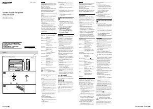
Power Connection Wires (not supplied)
Cables de conexión de alimentación (no suministrados)
to a metal point of the car
a un punto metálico del
automóvil
Fuse (25 A)
Fusible (25 A)
+12V car battery
Batería de automóvil de +12V
Car audio unit
Sistema de audio para
automóvil
Remote output*
1
Salida remota*
1
(REM OUT)
less than 450 mm
menos de 450 mm
*
2
*
1
If you have the factory original or some other car audio unit without a remote output for the amplifier, connect the remote
input terminal (REMOTE) to the accessory power supply.
*
1
Si dispone del sistema de audio para automóvil original de fábrica o de otro sistema sin una salida remota para el
amplificador, conecte el terminal de entrada remota (REMOTE) a la fuente de alimentación auxiliar.
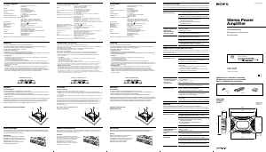
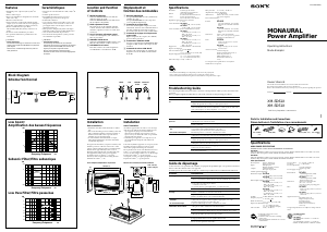
2-Speaker System (with Input Connection )
Sistema de 2 altavoces (con conexión de entrada )
Left speaker (min. 2 Ω)
Altavoz izquierdo (mín. 2 Ω)
Right speaker (min. 2 Ω)
Altavoz derecho (mín. 2 Ω)
1-Speaker System (with Input Connection )
Sistema de 1 altavoz (con conexión de entrada )
Note
Make sure that the line output from the car audio unit
is connected to the jack marked “L (BTL)” on the unit.
Right speaker
(min. 4 Ω)
Altavoz derecho
(mín. 4 Ω)
Left speaker
(min. 4 Ω)
Altavoz izquierdo
(mín. 4 Ω)
Nota
Asegúrese de que la salida de línea del sistema de
audio para automóvil está conectada a la toma con la
marca “L (BTL)” de la unidad.
Line Input Connection (with Speaker Connection , or )
Conexión de entrada de línea (con conexión de altavoces , ó )
LINE OUT
Car audio unit
Sistema de audio para
automóvil
Subwoofer (with Input Connection )
Altavoz potenciador de graves (con conexión de entrada )
Note
If you wish to use a subwoofer as the monaural
speaker, connect the speaker as illustrated above.
The output signals to the subwoofer will be the
combination of both right and left output signals.
Subwoofer (min. 4 Ω)
Altavoz potenciador de graves
(mín. 4 Ω)
Nota
Si desea utilizar el altavoz potenciador de graves
como altavoz monoaural, conecte el altavoz tal como
se muestra en la ilustración anterior. Las señales de
salida enviadas al altavoz potenciador de graves
serán una combinación de las señales de salida
derecha e izquierda.
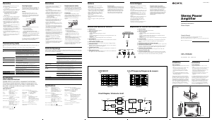
Dual Mode System (with a Bridged Subwoofer )
Sistema de modo dual (con altavoz potenciador de graves en puente )
C1 C2
L
Subwoofer
Altavoz potenciador de graves
Left speaker
Altavoz izquierdo
Right speaker
Altavoz derecho
For details on the values of C1, C2, L, refer to
“Table of crossover values for 6 dB/octave”.
Para obtener más información sobre los valores
de C1, C2 y L, consulte la “Tabla de valores de
cruce para 6 dB/octava”.
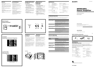
Line Input Connection (with Speaker Connection )
Conexión de entrada de línea (con conexión de altavoces )
Right channel
Canal derecho
Left channel
Canal izquierdo
LINE OUT
L (BTL) L (BTL)
Car audio unit
Sistema de audio para
automóvil
English
Connections
Cautions
ˎ
Before making any connections, disconnect the
ground terminal of the car battery to avoid short
circuits.
ˎ
Be sure to use speakers with an adequate
power rating. If you use small capacity speakers,
they may be damaged.
ˎ
This is a Phase-Inverted Amplifier.
ˎ
Do not connect the terminal of the speaker
system to the car chassis, and do not connect
the terminal of the right speaker with that of
the left speaker.
ˎ
Install the input and output cords away from the
power supply wire as running them close
together can generate some interference noise.
ˎ
This unit is a high powered amplifier. Therefore,
it may not perform to its full potential if used
with the speaker cords supplied with the car.
ˎ
If your car is equipped with a computer system
for navigation or some other purpose, do not
remove the ground wire from the car battery. If
you disconnect the wire, the computer memory
may be erased. To avoid short circuits when
making connections, disconnect the +12V power
supply wire until all the other wires have been
connected.
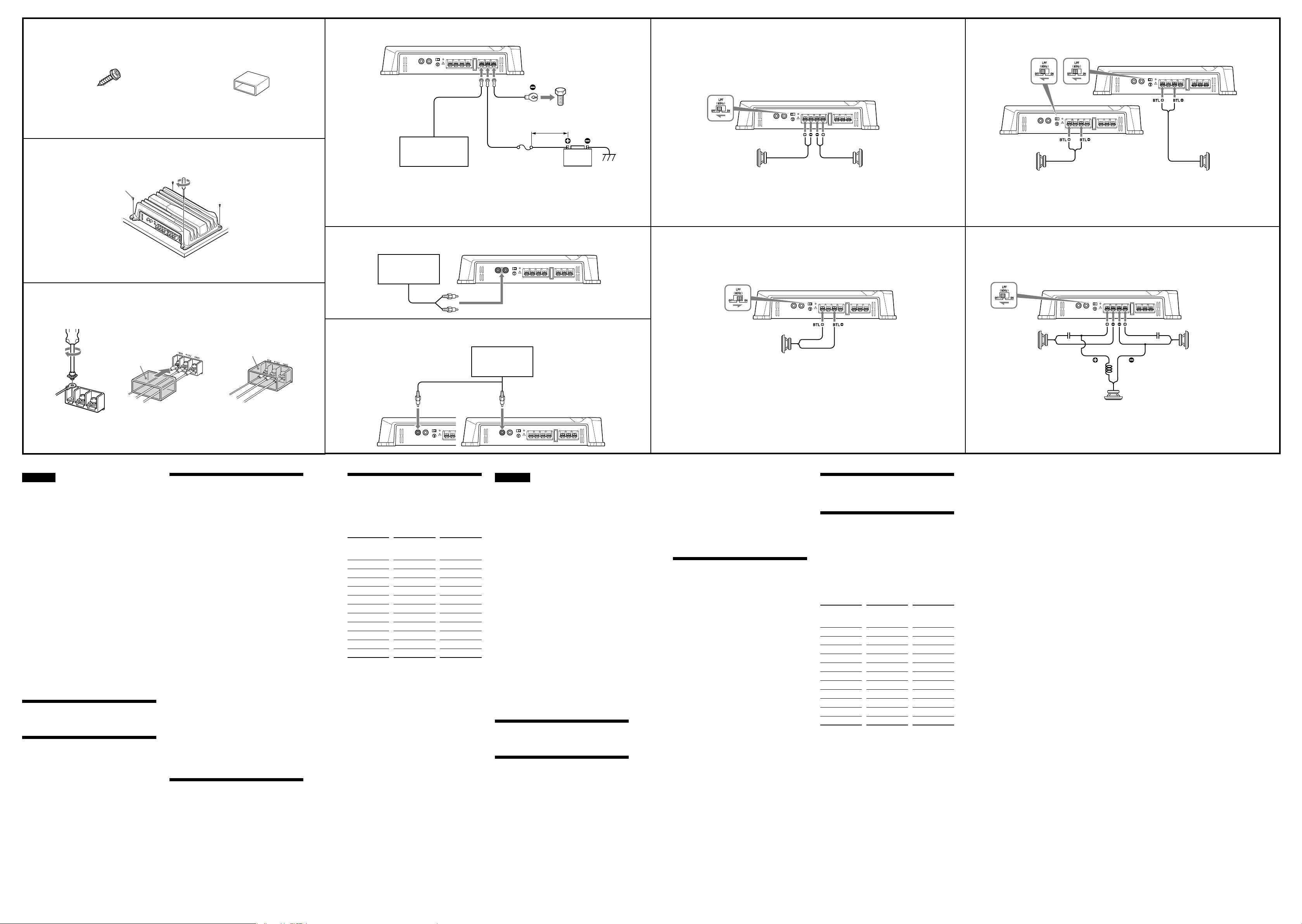
Parts for Installation and
Connections ()
Installation
Before Installation
ˎ
Mount the unit either inside the trunk or under a
seat.
ˎ
Choose the mounting location carefully so the
unit will not interfere with the normal
movements of the driver and it will not be
exposed to direct sunlight or hot air from the
heater.
ˎ
Do not install the unit under the floor carpet,
where the heat dissipation from the unit will be
considerably impaired.
Mount the unit ()
First, place the unit where you plan to install it,
and mark the positions of the 4 screw holes on
the mounting board (not supplied). Then drill a
3mm pilot hole at each mark and mount the unit
onto the board with the supplied mounting
screws. The mounting screws are all 20 mm long,
so make sure that the mounting board is thicker
than 20 mm.
Power connections
Make the terminal connections
()
Pass the wires through the cap, connect the wires,
then cover the terminals with the cap.
Note
When you tighten the screw, be careful not to apply
too much torque* as doing so may damage the
screw.
* The torque value should be less than 1 N•m.
Make the power connections
()
Notes on the power supply
ˎ
Connect the +12V power supply wire only after all
the other wires have been connected.
ˎ
Be sure to connect the ground wire of the unit
securely to a metal point of the car. A loose
connection may cause a malfunction of the
amplifier.
ˎ
Be sure to connect the remote control wire of the
car audio unit to the remote terminal.
ˎ
When using a car audio unit without a remote
output on the amplifier, connect the remote input
terminal (REMOTE) to the accessory power supply.
ˎ
Use a power supply wire with a fuse attached
(25 A).
ˎ
All power wires connected to the positive battery
post should be fused within 450 mm of the battery
post, and before they pass through any metal.
ˎ
Make sure that the vehicle’s battery wires
connected to the vehicle (ground to chassis)*
2
are
of a wire gauge at least equal to that of the main
power wire connected from the battery to the
amplifier.
ˎ
During full-power operation, a current of more than
25 A will run through the system. Therefore, make
sure that the wires to be connected to the +12V and
GND terminals of this unit are at least 14-Gauge
(AWG-14) or have a sectional area of more than
2mm
2
.
Input Connections
For details on the input connections, see and
.
Speaker Connections
Turn on or off the LPF switch at the unit rear.
For details on the speaker connections, see ,
, and .
Table of crossover values for 6 dB/
octave (4 Ω) (Speaker Connections )
Crossover
Frequency
unit: Hz
L
(coil)*
unit: mH
C1/C2
(capacitor)*
unit: µF
50 12.7 800
80 8.2 500
100 6.2 400
130 4.7 300
150 4.2 270
200 3.3 200
260 2.4 150
400 1.6 100
600 1.0 68
800 0.8 50
1,000 0.6 39
* Not supplied
Notes
ˎ
When using passive crossover networks in a
multi-speaker system, care must be taken as the
speaker system’s impedance should not be lower
than that of the suitable impedance for this unit.
ˎ
When you are installing a 12 decibels/octave
system in your car, the following points must be
considered. In a 12 decibels/octave system where
both a choke and capacitor are used in series to
form a circuit, great care must be taken when they
are connected. In such a circuit, there is going to be
an increase in the current which bypasses the
speaker with frequencies around the crossover
frequency. If audio signals continue to be fed into
the crossover frequency area, it may cause the
amplifier to become abnormally hot or the fuse to
blow. Also if the speaker is disconnected, a
series-resonant circuit will be formed by the choke
and the capacitor. In this case, the impedance in the
resonance area will decrease dramatically resulting
in a short circuit situation causing damage to the
amplifier. Therefore, make sure that a speaker is
connected to such a circuit at all times.
Español
Conexiones
Precaución
ˎ
Antes de realizar las conexiones, desconecte el
terminal de toma a tierra de la batería del
automóvil para evitar cortocircuitos.
ˎ
Asegúrese de utilizar altavoces con una
potencia nominal adecuada. Si emplea
altavoces de capacidad reducida, pueden
dañarse.
ˎ
Este amplificador es de fase invertida.
ˎ
No conecte el terminal del sistema de
altavoces al chasis del automóvil, ni el terminal
del altavoz derecho al del altavoz izquierdo.
ˎ
Instale los cables de entrada y salida alejados
del cable de la fuente de alimentación, ya que
en caso contrario puede generarse ruido por
interferencias.
ˎ
Esta unidad es un amplificador de alta potencia.
Por tanto, puede no funcionar a pleno
rendimiento si se utiliza con los cables de
altavoz suministrados con el automóvil.
ˎ
Si el automóvil está equipado con un sistema de
ordenador para la navegación o para otra
finalidad, no desconecte el conductor de toma a
tierra de la batería del automóvil. Si lo
desconecta, la memoria del ordenador puede
borrarse. Para evitar cortocircuitos al realizar las
conexiones, desconecte el cable de la fuente de
alimentación de +12V hasta conectar todos los
cables.
Componentes de instalación y
conexiones ()
Instalación
Antes de realizar la instalación
ˎ
Monte la unidad en el interior del maletero o
debajo de un asiento.
ˎ
Elija cuidadosamente el lugar de instalación de
forma que la unidad no dificulte las maniobras
normales del conductor y no quede expuesta a
la luz solar directa ni al aire caliente de la
calefacción.
ˎ
No instale la unidad debajo de la moqueta del
suelo, en cuyo caso la disipación de calor de la
misma disminuirá considerablemente.
Monte la unidad ()
En primer lugar, coloque la unidad donde tenga
previsto instalarla y marque sobre la superficie
del tablero de montaje (no suministrado) las
posiciones de los 4 orificios para los tornillos. A
continuación, perfore los orificios con un diámetro
de aproximadamente 3 mm y monte la unidad
sobre el tablero con los tornillos de montaje
suministrados. Ya que la longitud de estos
tornillos es de 20 mm, compruebe que el grosor
del tablero de montaje sea superior a 20 mm.
Conexiones de alimentación
Realice las conexiones de
terminal ()
Pase los cables a través de la cubierta, conéctelos
y cubra los terminales con dicha cubierta.
Nota
Al apretar el tornillo, tenga cuidado de no aplicar
demasiada fuerza de torsión*, ya que puede dañarlo.
* El valor de fuerza de torsión debe ser inferior a
1N•m.
Realice las conexiones de
alimentación ()
Notas sobre la fuente de alimentación
ˎ
Conecte el cable de la fuente de alimentación de
+12V sólo después de haber conectado los otros
cables.
ˎ
Asegúrese de conectar firmemente el cable de
toma a tierra de la unidad a un punto metálico del
automóvil. Una conexión floja puede causar fallos
de funcionamiento del amplificador.
ˎ
Compruebe que conecta el cable de control remoto
del sistema de audio para automóvil al terminal
remoto.
ˎ
Si utiliza un sistema de audio para automóvil sin
salida remota en el amplificador, conecte el
terminal de entrada remota (REMOTE) a la fuente
de alimentación auxiliar.
ˎ
Emplee el cable de la fuente de alimentación con
un fusible fijado (25 A).
ˎ
Todos los cables de alimentación conectados al
polo positivo de la batería deben conectarse a un
fusible situado a menos de 450 mm del polo de la
batería, y antes de pasar por ninguna pieza
metálica.
ˎ
Asegúrese de que los cables de la batería del
vehículo conectados al mismo (a la masa del
chasis)*
2
tienen una anchura igual o superior a la
del cable de alimentación principal que conecta la
batería con el amplificador.
ˎ
Durante el funcionamiento a pleno rendimiento,
fluye por el sistema una corriente superior a 25 A.
Por tanto, compruebe que los cables que va a
conectar a los terminales de +12V y GND de esta
unidad son del calibre 14 (AWG 14) como mínimo o
presentan un área de sección superior a 2 mm
2
.
Conexiones de entrada
Para obtener más información sobre las
conexiones de entrada, consulte e .
Conexiones de los altavoces
Encienda o apague el interruptor LPF situado en
la parte posterior de la unidad, como se muestra
a continuación.
Para obtener más información sobre las
conexiones de los altavoces, consulte , , ,
y .
Tabla de valores de cruce para 6 dB/
octava (4 Ω)
(Conexión de los altavoces )
Frecuencia de
cruce
unidad: Hz
L
(bobina)*
unidad: mH
C1/C2
(condensador)*
unidad: µF
50 12,7 800
80 8,2 500
100 6,2 400
130 4,7 300
150 4,2 270
200 3,3 200
260 2,4 150
400 1,6 100
600 1,0 68
800 0,8 50
1.000 0,6 39
* No suministrados
Notas
ˎ
Al utilizar redes de cruce pasivas en un sistema con
múltiples altavoces, es necesario asegurar que la
impedancia del sistema de altavoces no sea inferior
al valor de impedancia adecuado para esta unidad.
ˎ
Al instalar un sistema de 12 decibelios/octava en un
automóvil, hay que tener en cuenta los siguientes
puntos. En un sistema de 12 decibelios/octava
donde se emplea una bobina de choque y un
condensador en serie para formar un circuito, hay
que tener mucho cuidado al conectarlos. En los
circuitos de este tipo, se produce un aumento de la
corriente que pasa por alto el altavoz con
frecuencias próximas a la frecuencia de cruce. Si las
señales de audio siguen enviándose a la zona de
frecuencia de cruce, puede producirse un
sobrecalentamiento anormal del amplificador o
puede fundirse el fusible. Además, si se desconecta
el altavoz, se formará un circuito de resonancia en
serie compuesto por la bobina y el condensador. En
este caso, la impedancia del área de resonancia
disminuirá considerablemente, dando lugar a una
situación de cortocircuito y dañando el altavoz. Por
tanto, es necesario asegurar que haya un altavoz
conectado a un circuito en todo momento.

Praat mee over dit product
Laat hier weten wat jij vindt van de Sony XM-N502 Autoversterker. Als je een vraag hebt, lees dan eerst zorgvuldig de handleiding door. Een handleiding aanvragen kan via ons contactformulier.