
SONY XM-SD22X (GB,FR) 2-514-765-11 (1)SONY XM-SD22X (GB,FR) 2-514-765-11 (1)
ø 6 (
1
/4)
262 (10
3
/
8
)
403 (15
7
/8)
380 (15)
277 (11)
55
(2
1
/4)
2005 Sony Corporation
XM-SD22X
Owner’s Record
The model and serial numbers are located on the bottom of the unit.
Record the serial number in the space provided below.
Refer to these numbers whenever you call upon your Sony dealer regarding this product.
Model No. XM-SD22X Serial No.
•This unit is designed for negative ground 12 V
DC operation only.
•
Use speakers with suitable impedance.
— 2 – 8 Ω (stereo), 4 – 8 Ω (when used as a
bridging amplifier).
•Do not connect any active speakers (with built-in
amplifiers) to the speaker terminals of the unit.
Doing so may damage the amplifier and active
speakers.
•Avoid installing the unit in areas subject to:
— high temperatures such as from direct
sunlight or hot air from the heater
— rain or moisture
— dust or dirt
•If your car is parked in direct sunlight and there
is a considerable rise in temperature inside the
car, allow the unit to cool down before use.
•When installing the unit horizontally, be sure not
to cover the fins with the floor carpet etc.
•If this unit is placed too close to the car audio
unit or aerial, interference may occur. In this
case, relocate the amplifier away from the car
audio unit or aerial.
•If no power is being supplied to the car audio
unit, check the connections.
•This power amplifier employs a protection
circuit* to protect the transistors and speakers if
the amplifier malfunctions. Do not attempt to test
the protection circuits by covering the heat sink
or connecting improper loads.
•Do not use the unit on a weak battery as its
optimum performance depends on a good power
supply.
•For safety reasons, keep your car audio volume
moderate so that you can still hear sounds
outside your car.
•By default, the FILTER selector switch is in
“LPF” position. When connecting the full range
speaker, set to the “OFF” position.
Precautions
Fuse Replacement
If the fuse blows, check the power connection and
replace both the fuses. If the fuse blows again after
replacement, there may be an internal malfunction.
In such a case, consult your nearest Sony dealer.
Warning
When replacing the fuse, be sure to use one
matching the amperage stated above the fuse
holder. Never use a fuse with an amperage rating
exceeding the one supplied with the unit as this
could damage the unit.
∗ Protection circuit
This amplifier is provided with a protection circuit
that operates in the following cases:
— when the unit is overheated
— when a DC current is generated
— when the speaker terminals are short-circuited
The PROTECTOR indicator lights up in red and the
unit will shut down.
If this happens, turn off the connected
equipment, take out the cassette tape or disc, and
determine the cause of the malfunction. If the
amplifier has overheated, wait until the unit cools
down before use.
If you have any questions or problems concerning
your unit that are not covered in this manual,
please consult your nearest Sony dealer.
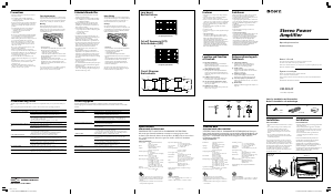
Stereo Power
Amplifier
Operating Instructions
Bruksanvisning
Installation
Before Installation
•Mount the unit either inside the trunk or under a
seat.
•Choose the mounting location carefully so the
unit will not interfere with the normal
movements of the driver and it will not be
exposed to direct sunlight or hot air from the
heater.
•Do not install the unit under the floor carpet,
where the heat dissipation from the unit will be
considerably impaired.
First, place the unit where you plan to install it,
and mark the positions of the four screw holes on
the surface of the mounting board (not supplied).
Then drill the holes approximately 3 mm (
1
/8 in) in
diameter and mount the unit onto the board with
the supplied mounting screws. The supplied
mounting screws are 15 mm (
19
/32 in) long.
Therefore, make sure that the mounting board is
thicker than 15 mm (
19
/32 in).
Specifications
AUDIO POWER SPECIFICATIONS
POWER OUTPUT AND TOTAL HARMONIC DISTORTION
200 watts per channel minimum continuous average power into
4 ohms, both channels driven from 20 Hz to 20 kHz with no more than
0.1 % total harmonic distortion per Car Audio Ad Hoc Committee
standards.
Other Specifications
Circuit system OTL (output transformerless)
circuit
Pulse power supply
Inputs RCA pin jacks
High level input connector
Outputs Speaker terminals
Through out pin jacks
Suitable speaker impedance
2 – 8 Ω (stereo)
4 – 8 Ω (when used as a bridging
amplifier)
Maximum outputs 400 W × 2 (at 4 Ω)
600 W × 2 (at 2 Ω)
1,200 W (BTL, at 4 Ω)
Rated outputs (supply voltage at 14.4 V)
200 W RMS × 2 (20 Hz – 20 kHz,
0.1 % THD + N, at 4 Ω)
250 W RMS × 2 (20 Hz – 20 kHz,
0.15 % THD + N, at 2 Ω)
500 W RMS (BTL) (20 Hz – 20
kHz, 0.15 % THD + N, at 4 Ω)
SN Ratio 93 dBA (Reference 1W into 4Ω)
Frequency response
5 Hz – 50 kHz (
dB)
Input level adjustment range
0.3 – 6.0 V (RCA pin jacks)
1.2 – 12.0 V (High level input)
Low-pass filter 50 – 300 Hz, –12 dB/oct
Low boost 0 – 10 dB (40 Hz)
Power requirements
12 V DC car battery
(negative ground)
Power supply voltage
10.5 – 16 V
Current drain at rated output: 48 A (at 4 Ω)
Remote input: 1 mA
Dimensions Approx. 403 × 55 × 277 mm
(15
7
/8 × 2
1
/4 × 11 in) (w/h/d) not
incl. projecting parts and controls
Mass Approx. 5.0 kg (11 lb 1 oz) not
incl. accessories
Supplied accessories
Mounting screws (4)
High level input cord (1)
Protection cap (1)
Design and specifications are subject to change
without notice.
Features
•Maximum power output of 400 W per channel
(at 4 Ω).
•This unit can be used as a bridging amplifier
with a maximum output of 1,200 W.
•Direct connection can be made with the speaker
output of your car audio unit if it is not equipped
with a line output (High level input connection).
•Built-in variable LPF (Low-pass filter) and low
boost circuit.
•Dual mode connection possible for a multi-
speaker system.
•Protection circuit.
•Pulse power supply* for stable, regulated output
power.
* Pulse power supply
This unit has a built-in power regulator which
converts the power supplied by the DC 12 V car
battery into high speed pulses using a
semiconductor switch. These pulses are stepped
up by the built-in pulse transformer and
separated into both positive and negative power
supplies before being converted into direct
current again. This light weight power supply
system provides a highly efficient power supply
with a low impedance output.
Troubleshooting Guide
The following checklist will assist in the correction of most problems which you may encounter with your
unit.
Before going through the checklist below, refer to the connection and operating procedures.
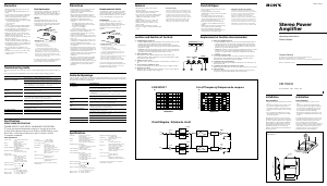
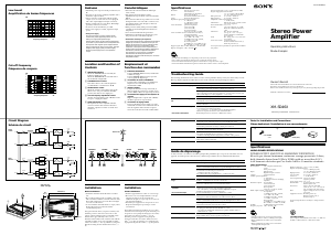
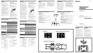
Circuit Diagram
Kretsschema
Unit: mm (in)
Enhet: mm
Low boost
Basförstärkare
Frequency/Frekvens
dB
Frequency/Frekvens
dB
Cut-off frequency (LPF)
Gränsfrekvens (LPF)
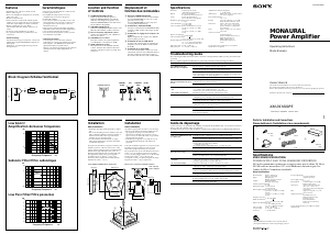
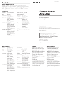
Parts for Installation and Connections
Delar för installation och anslutningar
12
(× 4)
3
368 (14
1
/2)
PROTECTOR
FILTER
OFF
LPF
LEVEL
LOW BOOST
(40Hz)
0 +10dB
6
0.3V
2
4
5.5
0.5
60
50 300Hz
170
110
260
10
0
-10
-20
-30
-40
-50
-60
-70
-80
10 100 1k
50Hz
170Hz
300Hz
LEVEL
LPF
Normal
AMP
Power
Lch
LEVEL
Inverted
AMP
Power
Rch
BTL
Lch
Rch
(BTL.)
LOW BOOST
LOW BOOST
Problem
Blue illumination does not light up.
The PROTECTOR indicator lights up in
red.
• The unit becomes abnormally hot.
• The sound is interrupted.
Alternator noise is heard.
The sound is muffled.
The sound is too low.
Cause/Solution
The fuse is blown. t Replace both the fuses with a new one.
The ground wire is not securely connected.
t Fasten the ground wire securely to a metal point of the car.
The voltage going into the remote terminal is too low.
• The connected car audio unit is not turned on.
t Turn on the
car audio unit.
• The system employs too many amplifiers. t Use a relay.
Check the battery voltage (10.5 – 16 V).
Turn off the power switch. The speaker outputs are short-circuited.
t Rectify the cause of the short circuit.
Turn off the power switch. Make sure the speaker cord and ground wire are
securely connected.
The unit heats up abnormally.
• Use speakers with suitable impedance.
t 2 – 8 Ω (stereo) , 4 – 8 Ω (when used as a bridging amplifier).
• Make sure to place the unit in a well ventilated location.
The thermal protector is activated. t Reduce the volume.
The power connecting wires are installed too close to the RCA pin cords.
t Keep the power connecting wires away from the RCA pin cords.
The ground wire is not securely connected.
t Fasten the ground wire securely to a metal point of the car.
Negative speaker cords are touching the car chassis.
t Keep the cords away from the car chassis.
The FILTER selector switch is set to the “LPF” position.
• By default, the FILTER selector switch is in “LPF” position.
t When connecting the full range speaker, set to the “OFF” position.
The LEVEL adjustment control is not appropriate. Turn the LEVEL
adjustment control in the clockwise direction.
ø 5 × 15 mm
Hz
Hz
1
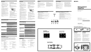
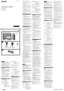
Location and Function
of Controls
1 PROTECTOR indicator
When the PROTECTOR is activated, the
indicator lights up in red.
When the PROTECTOR is activated refer to
the Troubleshooting Guide.
2 LEVEL adjustment control
The input level can be adjusted with this
control. Turn it in the clockwise direction
when the output level of the car audio unit
seems low.
3 LOW BOOST level control
Turn this control to boost the frequencies
around 40 Hz to a maximum of 10 dB.
4 Cut-off frequency adjustment control
Sets the cut-off frequency (50 – 300 Hz) for
the low-pass filter.
5 FILTER selector switch
When the switch is in the LPF position, the
filter is set to low-pass.
CEA2006 Standard
Power Output: 200 Watts RMS x 2 at 4 Ohms < 1%
THD+N
SN Ratio: 93 dBA (reference: 1 Watt into 4 Ohms)
• Packaging cushions do not use polystyrene foam.
• Lead-free solder is used for soldering certain parts.
• Halogenated flame retardants are not used in the
cabinets.
• Halogenated flame retardants are not used in the
certain printed wiring boards.
0,2 m (8 in)
•Enheten är avsedd att endast drivas med ett
negativt jordat 12 V batteri.
•
Använd högtalare med passande impedans.
— 2 – 8 Ω (stereo), 4 – 8 Ω (när den används
som bryggförstärkare).
•Koppla inte in några aktiva högtalare (med
inbyggda förstärkare) till enhetens högtalar-
anslutningar. I annat fall kan förstärkaren och
aktiva högtalare skadas.
•Undvik att placera enheten där den utsätts för:
— hög temperatur från direkt solbelysning eller
het luft från värmaren
— regn eller fukt
— damm eller smuts
•Om din bil står parkerad i direkt solljus och
temperaturen inuti bilen har ökat betydligt, låt
enheten svalna före användning.
•När enheten monteras horisontellt, se till att
kylflänsarna inte blockeras av golvmattan etc.
•Störningar kan uppstå om denna enhet placeras
alltför nära bilradion eller antennen. Om så är
fallet, omplacera förstärkaren så att den inte
befinner sig intill radion eller antennen.
•Om radion inte får ström, kontrollera först
anslutningarna.
•Denna effektförstärkare är försedd med en
skyddskrets* som skyddar transistorerna och
högtalarna om förstärkaren går sönder. Försök
inte att testa skyddskretsarna genom att täcka
över värmeavledaren eller att ansluta en felaktig
belastning.
•Använd inte enheten med ett svagt batteri
eftersom optimala prestanda beror på bra
strömförsörjning.
•Av säkerhetsskäl bör du hålla ljudvolymen på en
måttlig nivå så att du fortfarande kan uppfatta
ljud utanför bilen.
•Standardinställning för FILTER-väljaren är läge
“LPF”. När “full range”-högtalarna kopplas på
bör filtret ställas i läge “OFF”.
Säkerhetsföreskrifter
Byta säkring
Om säkringen utlöser, kontrollera elanslutningen
och byt ut båda säkringarna. Om säkringen utlöser
igen efter byte kan det finnas ett internt fel. I så
fall, kontakta närmaste Sony-återförsäljare.
Varning!
När säkringen ska bytas, kontrollera att du
använder en säkring med samma strömstyrka som
originalsäkringen. Använd aldrig en säkring med
högre strömstyrka än den som medföljer enheten
eftersom enheten kan skadas.
∗ Skyddskrets
Denna förstärkare är försedd med en skyddskrets
som träder i funktion i följande fall:
— när enheten är överhettad
— när likström alstras
— när högtalaranslutningarna kortsluts
PROTECTOR-indikatorn lyser då rött och enheten
slås av.
Om detta händer, slå ifrån ansluten utrustning, ta
ut kassettbandet eller skivan och ta reda på
orsaken till felet. Om förstärkaren har blivit
överhettad bör du vänta tills den har kylts av
innan den används igen.
Om du har några frågor eller problem som rör
enheten och som inte tas upp i bruksanvisningen,
kontakta närmaste Sonyåterförsäljare.
Felsökningsguide
Följande checklista kan vara användbar för att åtgärda problem som kan uppstå med enheten.
Innan du går igenom checklistan nedan, kontrollera rutinerna för hur man ansluter och använder
enheten.
Fel
Blå belysning tänds ej.
PROTECTOR -indikatorn tänds och
lyser rött.
• Enheten blir onormalt varm.
• Avbrott i ljudet.
Generatorbrus hörs.
Ljudet är dämpat.
För lågt ljud.
Orsak/åtgärd
Säkringen har löst ut. t Byt ut båda säkringarna mot nya.
Jordledaren är inte ordentligt ansluten.
t Anslut jordledaren ordentligt till metall på bilen.
Spänningen som går till fjärranslutningen är för låg.
• Den anslutna bilstereon är inte påslagen. t Sätt på bilstereon.
• För många förstärkare anslutna till systemet. t Använd ett relä.
Kontrollera batterispänningen (10,5 – 16 V).
Slå av strömbrytaren. Högtalarutgångarna är kortslutna.
t Åtgärda orsaken till kortslutningen.
Slå av strömbrytaren. Kontrollera att högtalarkabeln och jordledaren har
anslutits ordentligt.
Enheten blir onormalt varm.
• Använd högtalare med passande impedans.
t 2 – 8 Ω (stereo), 4 – 8 Ω (när den används som bryggförstärkare).
• Se till att placera enheten i ett utrymme som är ordentligt ventilerat.
Värmeskyddet är aktiverat. t Minska ljudvolymen.
Strömförsörjningskablarna har monterats alltför nära RCA-stiftkablarna.
t Se till att strömförsörjningskablarna hålls på avstånd från RCA-
stiftkablarna.
Jordledaren är inte ordentligt ansluten.
t Anslut jordledaren ordentligt till metall på bilen.
Negativa högtalarkablar är i kontakt med bilens chassi.
t Se till att kablarna hålls borta från bilens chassi.
FILTER-väljaren är ställd i läget “LPF”.
• Standardinställning för FILTER-väljaren är läge “LPF”.
t När “full range”-högtalarna kopplas in bör filtret ställas i läge “OFF”.
LEVEL-justeringen är inte lämplig. Vrid LEVEL-reglaget moturs.
Funktioner
•Maximal uteffekt är 400 W per kanal (vid 4 Ω).
•Denna enhet kan användas som en brygg-
förstärkare med en maximal uteffekt på 1,200 W.
•Direktanslutning kan göras till
högtalarutgångarna på din bilstereo om den inte
har en line-utgång (anslutning för högnivåingång)
•Inbyggt variabelt LPF (Lågpassfilter) och bas-
förstärkare
•Dubbelanslutning kan göras för flerkanals
högtalarsystem.
•Skyddskrets.
•Pulserad strömförsörjning* för stabil och
reglerad uteffekt.
* Pulserad strömförsörjning
Denna enhet har en inbyggd effektregulator som
omvandlar den effekt som levereras av bil-
batteriet (12 V DC) till pulser med hög hastighet
med hjälp av en halvledarswitch. Dessa pulser
ökas i amplitud genom den inbyggda puls-
transformatorn och delas upp i positiv och
negativ strömförsörjning innan de åter omvandlas
till likspänning. Detta lättvikts strömförsörjnings-
system genererar en ytterst effektiv ström-
försörjning med låg utimpedans.
Delarnas placering och
funktioner
1 PROTECTOR -indikator
När PROTECTOR är aktiverad lyser
indikatorn röd. När PROTECTOR är
aktiverad, se Felsökningsguiden.
2 LEVEL-reglage
Ingångsnivån kan justeras med detta
reglage. Vrid det medurs om utnivån från
bilstereon verkar låg.
3 LOW BOOST-reglage
Vrid på detta reglage för att förstärka
frekvenserna runt 40 Hz till max 10 dB.
4 Justeringsreglage för gränsfrekvens
Ställer in gränsfrekvensen (50 – 300 Hz) för
lågpassfiltret.
5 FILTER-väljare
Filtret är inställt för lågpass när väljaren är i
läge LPF.
Tekniska data
SPECIFIKATIONER FÖR LJUDEFFEKT
UTEFFEKT OCH TOTAL HARMONISK DISTORSION 200 Watt per
kanal med minimum kontinuerlig genomsnittlig effektförbrukning vid
4 Ohms belastning, båda kanalerna drivna från 20 Hz till 20 kHz med
högst 0,1 % total harmonisk distorsion enligt Car Audio Ad Hoc
Committe-standarden.
Övriga specifikationer
Kretsteknik OTL-krets (output trans-
formerless)
Pulserad strömförsörjning
Ingångar RCA-stiftuttag
Högnivå ingångskontakt
Utgångar Högtalaruttag
Genom utgångsstift
Lämplig högtalarimpedans
2 – 8 Ω (stereo)
4 – 8 Ω (när den används som
bryggförstärkare)
Max uteffekt 400 W × 2 (vid 4 Ω)
600 W × 2 (vid 2 Ω)
1,200 W (BTL, vid 4 Ω)
Märkspänningar (matningsspänning, 14,4 V)
200 W RMS × 2 (20 Hz – 20 kHz,
0,1 % THD + N, vid 4 Ω)
250 W RMS × 2 (20 Hz – 20 kHz,
0,15 % THD + N, vid 2 Ω)
500 W RMS (BTL) (20 Hz – 20 kHz,
0,15 % THD + N, vid 4 Ω)
Signal-brus-förhållande
93 dBA (Referens 1 W vid 4 Ω)
Frekvensåtergivning
5 Hz – 50 kHz ( dB)
Inställning av in-nivå
0,3 – 6,0 V (RCA stiftuttag)
1,2 – 12,0 V (Högnivåingång)
Lågpassfilter 50 – 300 Hz, –12 dB/okt
Basförstärkare 0 – 10 dB (40 Hz)
Strömkrav 12 V DC bilbatteri (negativ jord)
Spänningsförsörjning
10,5 - 16 V
Strömuttag vid märkeffekt: 48 A (vid 4 Ω)
Fjärringång: 1 mA
Dimensioner Ca. 403 × 55 × 277 mm (b/h/d) ej
inkl. utskjutande delar och
manöverorgan
Vikt Cirka 5,0 kg ej inkl. tillbehör
Medföljande tillbehör
Monteringsskruvar (4)
Inkabel för hög nivå (1)
Skyddslock (1)
Rätt till ändringar utan föregående meddelande
förbehålles.
CEA2006 Standard
Uteffekt: 200 Watt RMS x 2 vid 4 Ohm < 1 % THD+N
Signal-brus-förhållande: 93 dBA (referens: 1 Watt till
4 Ohm)
• Packkuddarna har inte polystyrenskum.
• Blyfritt lod används för att löda vissa delar.
• Flamhämmande medel av halogen används inte i
lådan.
• Flamhämmande medel av halogen används inte i
vissa kretskort.
Installation
Före installationen
•Montera enheten antingen inuti bagageutrymmet
eller under ett säte.
•Välj monteringsstället noggrant så att enheten
inte hindrar förarens normala rörelser och så att
den inte utsätts för direkt solljus eller varm luft
från värmaren.
•Placera inte enheten under golvmattan där
värmeavgivningen från enheten avsevärt
försämras.
Placera först enheten där du planerar att
montera den och märk ut läget för de fyra
skruvhålen på monteringsplattan (ej
medföljande). Borra därefter hålen med en
diameter på ca 3 mm och montera enheten på
plattan med hjälp av de medföljande
monteringsskruvarna. Monteringsskruvarna är
15 mm långa. Se därför till att monterings-
plattan är tjockare än 15 mm.
Ägarens noteringar
Modell- och serienummer finns på enhetens undersida.
Skriv in serienumret i utrymmet nedan.
Hänvisa till dessa nummer när du kontaktar din Sony-återförsäljare beträffande denna
produkt.
Modellnummer XM-SD22X Serienummer
01_N353_ensv.p65 05-08-22, 10.301
Black

Praat mee over dit product
Laat hier weten wat jij vindt van de Sony XM-SD22X Autoversterker. Als je een vraag hebt, lees dan eerst zorgvuldig de handleiding door. Een handleiding aanvragen kan via ons contactformulier.