
8 9TROUBLESHOOTING INSTALLATION
TROUBLESHOOTING
PROBLEM CAUSES REMEDY
The cooking zones are
not functioning.
• The desired heat setting is not set. • Set the heat setting.
• The fuse in the house’s electrical wiring
(fuse box) has been tripped.
• Check the fuse. If the fuse continues
to trip, please call an authorised
electrician.
The residual heat indicator is not
displaying anything.
• The cooking zone was only on for a short
period of time and is therefore not hot.
• If the cooking zone is hot, call the
Customer Service Department.
Red rings, limescale or water
rings, shiny metallic or other
discolouration, scratches/shadows,
bubbles or other miscellaneous
stains on ceramic glass
cooktop surfaces.
•
Cooktop surface has not been cleaned
correctly. Cleaning/maintenance of the
cooktop surface is not covered under
warranty. If a service call is placed to clean
the cooktop you will be charged for the visit.
• Use a ceramic glass cleaner such
as Cerapol.
Pitting of ceramic glass surface. • Spillovers of liquid with high
sugar content.
• These types of spills must be
removed immediately with a
special scraper for the glass. If not,
permanent damage to the cooktop
glass can occur which is not covered
under warranty.
The residual heat indicator is not
displaying anything.
• The cooking zone was only on for a short
time and is therefore not hot.
• If the cooking zone is supposed
to be hot, call the Customer
Service Department.
Outer ring on double ring element
won’t turn on.
• Control knob has not been turned
far enough.
• Turn control knob clockwise, past a
slight resistance. Refer instructions
on page 6.
If you are unable to remedy the problem by following
the above suggestions, please contact your dealer or
the Customer Care Department.
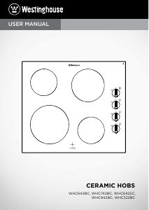
MODEL WHC642BC WHC742BC WHC642SC WHC942BC WHC322BC
PNC 949 163 433 949 163 437 949 163 434 949 163 438 949 163 432
Product
dimensions
(w x d mm)
590x520 700x520 606x505 900x520 320x520
Cut out
dimensions
(w x d mm)
560x490 560x490 560x490 880x490 300x490
Power (kW) 6.5 6.5 6.4 6.4 3.0
Service cord hardwired hardwired hardwired hardwired hardwired
Elements
No. of
zones
Watts
No. of
zones
Watts
No. of
zones
Watts
No. of
zones
Watts
No. of
zones
Watts
Front left 1 2300 1 2300 2
750/2200 2 750/2200 1 1200
Rear left 1 1200 1 1200 1 1200 1 1200 1 1800
Front right 1 1200 1 1200 1 1200 1 1800
Rear right 1 1800 1 1800 1 1800 1 1200
Total 4 6.5 4 6.5 4 6.4 4 6.4 2 3.0
WARNING
Repairs to the appliance are only to be carried out
by qualified service engineers due to the risk of
electric shock.
CAUTION
If the appliance has been wrongly operated or installed,
service calls may not be covered under the Warranty.
WARNING
To avoid any potential hazard, you must follow our
instructions when you install your appliance. Failure
to install the appliance correctly could invalidate any
warranty or liability claims and lead to prosecution.
• This appliance must be installed by an authorised
person according to all codes and regulations as
stated in the local municipal building code and other
relevant statutory regulations.
• Wiring connections must be in accordance with AS/
NZS 3000 Wiring Rules and any particular conditions
of the local authority.
• Wiring should be protected against mechanical
failure. Refer to AS/NZS3000 clauses 3.3.2.6, 3.9, 3.10
• A means of disconnection with a contact separation
of at least 3mm must be supplied in the fixed wiring.
• This appliance must be installed by an authorised
person according to all codes and regulations as
stated in the local municipal building code and other
relevant statutory regulations.
• The minimum distances to other appliances and units
are to be observed.
• Turn off the power at the mains before installing
this appliance.
• Supply cords must have a temperature rating not less
than 105°C.
• The surface temperature of the appliance exceeds
95°C. Underbench access must be restricted to
prevent a hazard.
• The clamping joints must be installed by a
qualified electrician.
• The electrical schematic must be observed.
Electrical connection
Before connecting, check that the nominal voltage of the
appliance stated on the rating plate, corresponds to the
available supply voltage. The rating plate is located on the
lower casing of the hob.
The hob is to be connected to the mains using a device
that allows the appliance to be disconnected from the
mains at all poles with a contact opening width of at least
3mm. eg. automatic line protecting cut-out, earth leakage
trips or fuse. A cable with a minimum temperature
rating of V90HT or higher must be used as the mains
connecting cable.
The connection must be carried out as shown in the
diagram. The connecting links should be fitted according
to the appropriate connection diagram. The earth lead is
connected to terminal.
Connection cable
• Use the correct mains cable of type H05BB-F Tmax
90°C (or higher) for a single phase or two phase
connection.
• Replace the damaged mains cable with a special
cable (type H05BB-F TMAX 90°C or higher)
WHC323BC: 3 x 1.5mm² with and all-pole 16A breaker.
The others: 3 x 2.5mm
2
with an all-pole 25A breaker.
Speak to your local Service Centre.
• The earth cord (green/yellow cable) must be 2cm
longer than phase and neutral cable (blue and brown
cables).
• The cable conditions must be in accordance with
regulations and the terminal screws tightened
securely.
• The connecting cable is to be secured with the mains
cable cleat and the covering closed by pressing firmly
(lock into place).
• Before switching on for the first time, any protective
foil or stickers must be removed from the glass
ceramic surface.
IMPORTANT
Once connected to the mains supply, check that all the
cooking zones are ready for use by briefly switching each
on in turn at the maximum setting.
INSTALLING YOUR APPLIANCE
TECHNICAL DATA





Praat mee over dit product
Laat hier weten wat jij vindt van de Westinghouse WHC642SC Kookplaat. Als je een vraag hebt, lees dan eerst zorgvuldig de handleiding door. Een handleiding aanvragen kan via ons contactformulier.