1. Use and Application
Temp. Range 10…60°C
• direct floor heating
• floor storage heating
• surface heating
• air conditioning etc.
2. Installation instructions
The cover (14) of the timer housing should be lifted up. After remo-
ving the setting knob (13) for the daytime temperature setting (1) and
loosening the fixing screw (3) the upper part can be turned in the di-
rection of the timer and removed.
The floor heating thermostat can then be fitted to any commercially
available flush-mounted socket with horizontal fixing holes or alter-
natively directly onto the wall. When selecting a suitable place for mo-
unting, draughts and warm air currents should be avoided, and you
should allow a free circulation of air. Recommended mounting height:
approx 1.5m
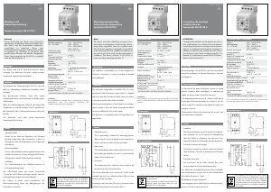
3. Wiring Diagram
Important Notice:
Please read carefully the technical data on the inside of the cover of
the equipment.
Insert insulated wires in corresponding screw terminals and connect
as shown in the wiring diagram. Once the electrical connection has
been made replace the upper housing and screws in (3), and replace
the daytime temperature setting button (13).
4. Changeover setting. Temperature set-back
For daily programme Model 52527
First lift off cover (14).
Set-back temperature ”on“ = blue tappet
Set-back temperature ”off“ = red tappet
The tappets are factory set to come at 22.00 and switch off at 06.00.
These times can be changed if required by adjusting the tappets. The
tappets are pressed upwards and can be moved around the dial until
the disered switching times are set.
For the weekly programme Model 52528
Procedure is as for setting the daily programme. Note the following
abbreviations for the days of the week:
Beginning with Mo = Monday, Di = Thuesday, Mi = Wednesday, Do =
Thursday, Fr = Friday, Sa = Saturday, So = Sunday.
The minimum time setting is one hour.
5. Setting the timer
For the daily programme
To set the timer first remove the cover (14). Set the time by turning
the minute hand clockwise. Take care to ensure that the indicator ar-
row (11) next to the day dial (8) is showing the setting time on the
dial.
Example
Setting time = 15.00
Turn the minute hand until the number 15 on the 24 hour dial is at
the indicator arrow.
For the weekly programme
To set the timer first remove the cover (14). Set the time by turning
the minute hand clockwise. Take care to ensure that the indicator ar-
row (11) is showing the set time on the week dial. Take care that the
correct day of the week as well as the time is indicated.
Example:
Setting time = 15.00, Tuesday
Turn the minute hand until the number 15 and Di are the indicator
arrow on the week dial.
6. Recommended day and night temperature settings
The temperature, which you can require in the living area, is set by
means of the daytime temperature setting knob (13). A setting on the
red point is recommended, corresponding to a room temperature of
approx. 20 deg C. The night set-back temperature can be set by me-
ans of the adjustable potentiometer (2). It is recommended to set a
set-back temperature of approx. 3 to 4 K. Naturally other settings are
possible, if required.
7. Problems – Timer
No night set-back: are the switches set for the correct time? Is
the setting sequence correct for 2 or more heating programmes
– red-blue – red-blue?
Is the position on the setting knob correct?
8. To reduce the setting temperature range of the
daytime temperature
The room temperature setting knob is factory set on the Range 1…6.
See illustration 2. On the underside of the setting knob there are 2 re-
stricting rings, with a setting range of 5…35 deg C. When narrowing
the setting range please do so in accordance with the following dia-
gram.
Reducing the range in the setting knob.
Using the restricting rings you can narrow the setting range as desi-
red, for example within the range 3 to 5
Range stops inside setting knob
8.1 Setting procedure
• First select the desired limits:
Example Upper: 5 Lower: 3
• Caution:
First switch setting knob to approx. the middle of the desired
setting range.
Example:
Mid point of 3 and 5 is ●
• Then remove the setting knob to ● and remove.
• Set red setting ring to upper temperature limit:
To set upper limit to 5
Turn anti-clockwise. Note: instructions refer to the outer num-
bers of the scale.
Insert tip of ball point pen into hole and turn red ring left on to 25
deg C (max scale) (see diagram). Illustration 3.
• Set the blue setting ring to
lower temperature limit:
To set lower limit to 3.
Turn clockwise. Instructions refer to the inner numbers of the
scale.
Insert tip of ball point pen and turn blue ring onto 15 deg C. (min
scale) (see diagram). See illustration 4
• Replace setting knob with setting at
●.
The indicator should now show the middle of new setting range:
see Point 2.
9. Programme selector switch
É selected daytime temperatur ”on“
Ñ selected night-time temperatur ”on“
> automatic changeover between day- an night temperature
10. Technical Data
Thermostat
Typ Daily Programme Weekly Programme
Order description FRe-UTQ 52527 FRe-UTQ 525 28
Computer ref No. 10…60 deg C 052527141860 052528141860
Voltage 230V 230V
195…253V 195…253V
Switching current approx. 7 VA approx. 7VA
Current cos ϕ 1 16 A cos ϕ 1 16 A
cos ϕ 0,6 4 A cos ϕ 0,6 4 A
Output relay contact 1 N/O 1 N/O
Temperature range 10…60 deg C 10…60 deg C
Range reduction for daytime temperature in setting knob in setting knob
Setting temp differential 0,8K ± 0,5K 0,8K ± 0,5K
Changeover setting every 10 mins possible every hour possible
Shortest changeover time on/off 30 mins 3 hours
Tappets 6 (3 x on/off) 18 (9 x on/off)
Timer Quartz clock screwed to base plate
Battery reserve After voltage failure greater than 150 hours (Loading time 140 hours)
Signal lamp ”heating“ Standard Standard
Housing protection type IP 30 (DIN VDE 0470 T1) IP 30 (DIN VDE 0470 T1)
Apparatus protection class II to VDE 0631 II to VDE 0631
Humidity class F to DIN 40040 F to DIN 40040
Weight approx. 180 g approx. 180 g
Storing temperature -25…70 deg C -25…70 deg C
Operation temperature 0…+40 deg C 0…+40 deg C
Remote Sensor
Order description F 193720
Computer ref No. 000193720001
Sensor element NTC
Sensor cable PVC – 2 core x 0,50 mm
2
Length 4 m
Protection class IP 68 to DIN VDE 0470 T1
Ambient temperature -25…70 deg C
Sensor colour code white
The sensor cable can be lengthened to 50 m if required with a two wire cable with a diameter of 1,5 mm
2
, without affecting the accuracy of the sensor.
Sensor specification and characteristics
Sensor temperature 10…60°C (kΩ) (V)
10 dec C 66,8 3,7
20 deg C 413 3,4
30 deg C 26,3 2,9
40 deg C 17,1 2,5
50 deg C 11,3 2,0
60 deg C 7,5 1,5
The resistance values can only be measured when sensor is connected, the current only flows when the sensor is in operation when connencted to
circuit.
Warning:In case of failure note mains current can be present at the sensor!
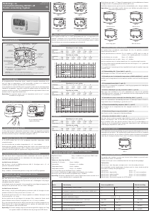
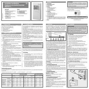
11. Dimensions
Contol unit
K
Operating Instructions
for floor heating thermostat
with quarz timer
Model 52527 and 52528
Caution
If replacing an existing thermostat, Model 52521, using the old
sensor (Colour Code:black) R18 must be disconnected (by coun-
ting one leg of the resistor).
Caution
The unit should only be installed and set up by an qualified en-
gineer. The enclosed safety precautions should be observed.
Other application options, dimensions & in particular technical
specifications are given in our information sheet.
The floor heating thermostats are fitted with suppressors in accor-
dance with VDE 0875-A2 and EEC Guidelines 82/499/EWG rela-
ting to radio inteference grade N.
If the unit is used in combination with other appliances, care
should be taken in case any of the appliances causes radio interfe-
rence. Installation must be in accordance with the appropriate re-
gulations.
Caution:
• The switch in the thermostat breaks the circuit but not
the hea-
ting resistance
• If an auxiliary circuit is used the mains voltage should be swit-
ched off (remove fuse)
• In the event of a sensor disconnection or sensor short circuit the
relay contact is not engaged; nor in the event off an appliance
breakdown. The Thermostat is self monitoring.
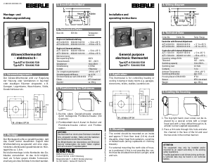
Fig. 1
1 Set scale for day temperature
2 Set scale for night temperature
3 Fixing screw for cover
4 Lamp ”Heating“
5 Slide switch program selection
6 Control of clock run
7 Minute disc
8 Daily or weekly disc
9 Tappets
10 Reserve tappets
11 Mark for time set
12 Indicator of switching operation
13 Setting knob
14 Cover
15 2 fixing screws (for clock movement)
Fig. 2
Delivered with a range of 1 to 6
Fig. 4
Ring min. adjusted in direction of arrow to 15 °C
Fig. 3
Ring max. adjusted in direction of arrow to
K
EBERLE Controls GmbH · Postfach 130153 · D-90113 Nürnberg
Klingenhofstraße 71 · D-90411 Nürnberg/Germany
Telefon 0911/5693-0 · Telefax 0911/5693-214
Errors possible
Sensor


Praat mee over dit product
Laat hier weten wat jij vindt van de Eberle 525 28 Thermostaat. Als je een vraag hebt, lees dan eerst zorgvuldig de handleiding door. Een handleiding aanvragen kan via ons contactformulier.
beantwoord | Ik vind dit nuttig (0)