Handleiding Horstmann Electronic 7 Thermostaat

Handleiding voor je Horstmann Electronic 7 Thermostaat nodig? Hieronder kun je de handleiding gratis bekijken en downloaden als PDF in het Nederlands en/of Engels. Dit product heeft 2 veelgestelde vragen, 1 comment en heeft 0 stemmen. Is dit niet de handleiding die je zoekt, neem dan contact met ons op.

Is je product kapot en biedt de handleiding geen oplossing meer? Dan kun je voor reparatie gratis terecht bij Repair Café.

Handleiding

Loading…

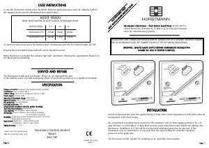
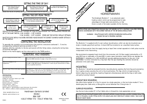
CONNECTIONS
Use a three-core cable with a minimum conductor size of 1.0mm
2
for a 2kW heater, or 1.5mm
2
for a
3kW heater to connect the unit to the supply. Connect the incoming wires to the terminal block as
follows;
TERMINAL 1 - LIVE in
TERMINAL 2 - NEUTRAL in
TERMINAL 3 - NEUTRAL(s) outtoimmersionheater(s)
TERMINAL 4 - LIVE out to Boost immersion heater
TERMINAL 5 - LIVE out to Off-Peak immersion heater
Clamp all surface wiring adjacent to the box or use trunking where appropriate. Secure the heat
resistant flexible cords from the immersion heaters using the cable clamp in the box.
SINGLE ELEMENT IMMERSION HEATERS
The 3 core flexible cord should be heat-resistant and rated to 85
o
C.
TERMINAL 4 (Boost live output) should be connected to TERMINAL 5(Off-Peak live output) and to the
immersion heater.
The Neutral connection should go to TERMINAL3 and the Earth connection to the EARTH TERMINALS.
DUAL ELEMENT IMMERSION HEATERS
The elements should be controlled through separate thermostats. In practice the thermostat for the
top short element is usually set
5-10
o
Cless than the thermostat for the long Off-Peak element.
The 3 core flexible cords should be heat-resistant and rated
85
o
C.
TERMINAL 4 (boost live output) should be connected to the short element and TERMINAL 5(Off-Peak
live output) to the long element.
The Neutral connections should go to TERMINAL 3and the Earth connection to the EARTH TERMINALS.
TWIN IMMERSION HEATERS
The thermostat for the top immersion element should be set lower than the thermostat for the
bottom immersion heater.
The 3 core flexible cords should be heat-resistant and rated
85
o
C.TERMINAL 4(boost live output)
should be connected to the top immersion heater and TERMINAL 5(off-peak live output)to the bottom
immersion heater. The two Neutral connections should go to TERMINAL 3and the Earth connections to
the EARTH TERMINALS
COMMISSIONING INSTRUCTIONS
SETTING THE CONTROLLER
A feature of this controller is that it allows the time of day and Off-Peak switching times to be set
before the unit is finally installed and powered up.
COMMISSIONING SWITCH
The commissioning switch which is on the back of the unit must now be set to achieve correct
operation of the controller and battery reserve. The display will remain blank with the switch in the
OFF position.
RESETTING THE ELECTRONIC 7
Before installing the off-peak heating periods it is important to reset the unit, this is achieved by
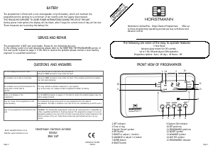
simultaneously pressing the Boost, Summer/Winter, HrsandMins buttons together. The Boost
selection switch must be in the Manual Boost Position.
Electronic equipment can sometimes be affected by sudden changes of atmosphere, this can result in
Display being fogged or Reset function failure. If this happens leave the unit switched on for 15
minutes and repeat the RESET function.
BOOST
SUMMER/
WINTER
HRS MINS
MANUAL BOOST
TIMED BOOST
BOOST SELECTION
SWITCHPOSITION - GMT or GMT/BST
It is essential that the correct commissioning switch position is selected. Incorrect setting of the
commissioning switch may result in inefficient use of the available Off-Peak supply.
GMT ONLY- Switching will always take place at GMTtimes (summer and winter).
GMT/BST- Switching time will be changed by one hour, when the user presses
SUMMER/WINTERbutton on the face of the unit. In the GMT/BSTmode the clock display will match
the actual switching time.
If connection is to be made where a 2-Rate electricity meter is controlled by a Radio Teleswitch or
other equipment, which control tariffs remotely or seasonally, it is essential that before setting the
commissioning switch you find out how the off-peak times are controlled.
The Customer Service Centre of your Electricity Supplier will confirm information regarding Off-Peak
electricity timing and the switching method used for your area. (see below)
GMT ONLY- Set the switch in the GMT position, switching will always take place at GMT
times (summer and winter).
GMT/BST- Set the commissioning switch in the GMT/BST position. Switching time will be
changed by one hour, when the user presses SUMMER/WINTERbutton on the face of the unit. In the
GMT/BSTmode the clock display will match the actual switching time.
On installations where the 2-Rate electricity meter is controlled by a mechanical Tariff Timeswitch the
commissioning switch should be set to GMT ONLY.
PAGE 2 PAGE 3
When wiring is complete ensure that all terminal screws,
including the earth terminal screws are securely tightened
to achieve a minimum torque of .75Nm.
Download de handleiding in het Nederlands en/of Engels (PDF, 0.1 MB)
(Denk aan het milieu en print deze handleiding alleen als dat echt noodzakelijk is)

Loading…

Beoordeling

Laat ons weten wat je van de Horstmann Electronic 7 Thermostaat vindt door een beoordeling achter te laten. Wil je je ervaringen met dit product delen of een vraag stellen? Laat dan een bericht achter onderaan de pagina.
Bent u tevreden over de Horstmann Electronic 7 Thermostaat?
Ja Nee
Beoordeel dit product als eerste
0 stemmen

Praat mee over dit product

Laat hier weten wat jij vindt van de Horstmann Electronic 7 Thermostaat. Als je een vraag hebt, lees dan eerst zorgvuldig de handleiding door. Een handleiding aanvragen kan via ons contactformulier.

Ness L 10-07-2020
Hallo, mijn Horstman-ketel werkte tot een stroomstoring. Na stroomonderbreking werd de tijd gereset en werkte de ketel tijdens de daluren, bijv. 2-7 uur. Ik heb dit gecontroleerd en bevestigd. Wat ik niet begrijp is waarom het water helemaal niet warm is als de ketel werkt, wat kan de reden zijn dat er geen warm water is? In de ochtend voelt de ketel warm aan. Om het even welk advies zou zeer gewaardeerd worden.

beantwoord | Ik vind dit nuttig (0) (Vertaald door Google)

Meer over deze handleiding

We begrijpen dat het prettig is om een papieren handleiding te hebben voor je Horstmann Electronic 7 Thermostaat. Je kunt de handleiding bij ons altijd downloaden en daarna zelf printen. Indien je graag een originele handleiding wilt hebben, raden we je aan contact op te nemen met Horstmann. Zij kunnen wellicht nog voorzien in een originele handleiding. Zoek je de handleiding van Horstmann Electronic 7 Thermostaat in een andere taal? Kies op de homepage je taal naar keuze en zoek daarna op het modelnummer om te zien of we deze beschikbaar hebben.

Specificaties

Merk Horstmann
Model Electronic 7
Categorie Thermostaten
Bestandstype PDF
Bestandsgrootte 0.1 MB

Alle handleidingen voor Horstmann Thermostaten
Meer handleidingen voor Thermostaten

Veelgestelde vragen over Horstmann Electronic 7 Thermostaat

Ons supportteam zoekt dagelijks naar nuttige productinformatie en antwoorden op veelgestelde vragen. Als er onverhoopt toch een onjuistheid tussen onze veelgestelde vragen staat, laat het ons dan weten via het contactformulier.

Wat is de dode zone van een thermostaat? Geverifieerd

Veel modernere thermostaten hebben een dode zone. Als de temperatuur minder dan ongeveer 4°C afwijkt van de ingestelde temperatuur, dan zal het systeem niet verwarmen of koelen. Deze zogenoemnde dode zone van de thermostaat voorkomt dat het systeem te vaak aan- en afslaat en bespaart zo energie.

Ik vind dit nuttig (1588) Lees meer

Wat is de beste locatie om een thermostaat te plaatsen? Geverifieerd

De beste plek voor een thermostaat is ongeveer 1,5 meter van de grond. Plaats de thermostaat niet in de buurt van een radiator of andere apparatuur die warmte afgeeft of in direct zonlicht. Kies een kamer die vaak wordt gebruikt. In veel gevallen is dit de woonkamer.

Ik vind dit nuttig (992) Lees meer
Handleiding Horstmann Electronic 7 Thermostaat

Gerelateerde producten

Gerelateerde categorieën