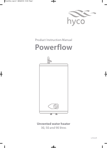
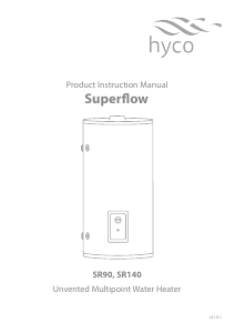
Handleiding Hyco PF90LC Powerflow Boiler

Handleiding voor je Hyco PF90LC Powerflow Boiler nodig? Hieronder kun je de handleiding gratis bekijken en downloaden als PDF in het Nederlands en/of Engels. Dit product heeft 5 veelgestelde vragen, 0 comments en heeft 0 stemmen. Is dit niet de handleiding die je zoekt, neem dan contact met ons op.

Is je product kapot en biedt de handleiding geen oplossing meer? Dan kun je voor reparatie gratis terecht bij Repair Café.

Handleiding

Loading…

Product Instruction Manual
Pow erflow
Unvented water heater
30, 50 and 90 litres
v15.6/5
Powerflow_Layout 1 28/06/2015 10:09 Page 1
Thank you for purchasing a Powerflow series unvented electric water heater. The Powerflow is
suitable for hand washing and dishwashing where a number of hot water outlets are required
such as kitchens, schools, restaurants, washrooms and offices. The Powerflow is the ideal solution
for light industrial, commercial and light domestic hot water requirements. Please read and
understand these instructions before commencing installation, and leave them with the user
when installation is complete.
1. Important safety points
Installation must be undertaken by a competent installer trained in the installation of unvented water
heating systems in accordance with building regulations G3.
Building regulations G3 requires a temperature and pressure relief valve to be factory fitted. This must
not be removed or blocked in any way.
Installation must comply with the latest edition of the IEE wiring regulations.
These units are very heavy. They must be securely fastened to a suitably strong wall using the fixings
supplied. Remember to allow for the weight of the water (one KG per litre of capacity) when assessing
the suitability of the wall.
2. Installation
Overview
Components Checklist
Expansion Vessel 3/4" MBSP, precharge pressure 3.5 bar
Pressure Reducing Valve, factory set at 3 bar
Single Check Valve 15mm x 15mm compression
Pressure (expansion) Relief Valve 1/2" BSP male inlet, 1/2" BSP female discharge, factory set at 6 bar
Tundish 15mm x 22mm
This unit must be installed vertically, with the pipes pointing downwards and the temperature and
pressure relief valve at the top.
Ensure the wall is strong enough to support the heater, including the weight of the water when full.
This heater is not suitable for outdoor installation.
Do not install where there is any risk of freezing.
The heater is bulky and heavy, Do not attempt to lift alone.
Powerflow_Layout 1 28/06/2015 10:09 Page 2
Plan your installation carefully and choose a suitable position for the heater, allowing suitable space for
accessories such expansion vessels, pipework and subsequent maintenance.
See schematic Diagram 1 for the correct relative positions of the components.
Fit all the components supplied, components may be supplied loose or connected to a mainfold.
The manifold aids installation but does not alter the relative positions of the components.
Do not remove the factory fitted temperature and pressure relief valve.
Ensure in particular that there are no valves of any kind between the expansion relief vlave and the heater.
Allow at least 400mm of space above and below the unity to permit for maintenance.
Observe flow direction arrows on components.
Wall mounting
Drill holes for supplied heavy duty bolts to wall at the spacings shown in the table below (also See Diagram 2).
Insert bolt hooks and tighten ensuring that they are secure then hang heater on the protruding hooks.
Temperature and
Pressure Relief Valve
POWERFLOW
Hot
Drain Cock
To Drain (Waste)
Pressure
(Expansion)
Relief Valve
Expansion
Ve ss el
Check
Valve
Balanced
Cold W ater
Draw O
Pressure
Reducing Valve
Service
Valve
Cold W ater
Mains
Diagram 1
B
A
Diagram 2
Model
Ve
rtical
Bolt
Spacing A (mm)
Horizontal Bolt
Spacing B (mm)
PF30L 270320
PF50L 52
0320
PF90L 430320
Safety Device
Tundish
600mm MAXIMUM
Metal Discharge Pipe (D1) from
Temperature Relief to Tundish
Discharge Below
Fixed Grating
300mm MINIMUM
Metal Discharge Pipe (D2) from
Tundish with Continuous Fall
Fixed Grating
Trapped Gully
Sizing of D2 Copper Discharge pipe for common temperature relief valve outlet size
Valve
outlet
size
Minimum size of
discharge pipe (D1)
Minimum size of
discharge pipe (D2)
from Tundish
Maximum resistance allowed,
expressed as a length of straight
pipe (I.E. no elbows or bends)
Resistance
created by each
elbow or bend
m8.0m9otpumm22mm512/1G
28mm up to 18m 1.0m
m4.1m72ot*mm53
Diagram 4
Element ange -
Remove to access anode
Thermostat
Thermal cutout -
Press here to reset
H
Diagram 3
WD
Temperature and
Pressure Relief Valve
POWERFLOW
Hot
Drain Cock
To Drain (Waste)
Pressure
(Expansion)
Relief Valve
Expansion
Ve ss el
Check
Valve
Balanced
Cold W ater
Draw O
Pressure
Reducing Valve
Service
Valve
Cold W ater
Mains
Diagram 1
B
A
Diagram 2
Model
Vertical Bolt
Spacing A (mm)
Horizontal Bolt
Spacing B (mm)
PF30LC
270320
PF50LC
520320
PF90LC
430320
Safety Device
Tundish
600mm MAXIMUM
Metal Discharge Pipe (D1) from
Temperature Relief to Tundish
Discharge Below
Fixed Grating
300mm MINIMUM
Metal Discharge Pipe (D2) from
Tundish with Continuous Fall
Fixed Grating
Trapped Gully
Sizing of D2 Copper Discharge pipe for common temperature relief valve outlet size
Valve
outlet
size
Minimum size of
discharge pipe (D1)
Minimum size of
discharge pipe (D2)
from Tun d i s h
Maximum resistance allowed,
expressed as a length of straight
pipe (I.E. no elbows or bends)
Resistance
created by each
elbow or bend
m8.0m9otpumm22mm512/1G
28mm up to 18m 1.0m
m4.1m72ot*mm53
Diagram 4
Element ange -
Remove to access anode
Thermostat
Thermal cutout -
Press here to reset
H
Diagram 3
WD
Powerflow_Layout 1 28/06/2015 10:09 Page 3
Plumbing connections
Connect ALL the plumbing valves in the sequence shown in diagram 1.
The cold water inlet to the heater is marked BLUE and the hot water outlet is marked RED.
Observe flow direction arrows on supplied valves.
The drain valve must be fitted close to the COLD inlet to allow drain down if necessary.
An isolating valve should be fitted UPSTREAM of all of the valves to allow the heater to be maintained
without impacting on other facilities.
Do NOT fit a service or other valves between the heater and the pressure relief (safety) valve as this
could impede its correct operation.
The pressure reducing valve is factory set at 3 bar. If a balanced cold water draw off is required this should
be tee-ed off down stream of this valve.
A balanced cold water feed is recommended as it ensures hot and cold water is supplied at the same
pressure. Some mixer taps and thermostatic showers require hot and cold water to be to be at the same
pressure for correct operation.
The expansion vessel supplied must be supported using a bracket or similar fixing. Do not rely on the
pipework alone – it will not be strong enough. The orientation of the vessel is not important.
When all valves are correctly fitted, open a hot tap and wait until the water flow is steady and without
traces of air. Close the tap to allow the system to reach full pressure and carefully check system for leaks.
Control valves may be supplied loosely connected for identification purposes, but these joins have
not been leak tested. This must be done at installation.
It is essential to also check the temperature pressure reflief valve connection to the heater for leaks.
Note that a leak from the temperature and pressure reflief vlve may not be immediately obvious, as
the connection is at the top of the heater and leaking water may in the first instance run down the
pipework and collect in the heater insulation.
Discharge pipe connections
This product falls within the scope of Building Regulation G3 which stipulates certain conditions relating to
the way any water discharge from relief valves is transported away.
These conditions are designed to ensure that any discharge will not present a hazard to people or to property,
and that any discharge is clearly visible so that the underlying cause is likely to be rectified promptly.
The essential requirement of G3 in relation to water discharge is that the discharge pipe MUST terminate in a
safe, visible position.
In achieving this aim the G3 regulations strongly recommended that:
The tundish is located within 500mm of the Temperature and Pressure Relief valve and it is wherever
possible oriented vertically. It must be visible to occupants and positioned away from electrical devices.
The discharge pipe has a vertical fall of at least 300mm immediately below the tundish.
The discharge pipe below the tundish is at least 22mm diameter (i.e. one size larger than the Temperature
and Pressure Relief valve outlet).
The discharge pipe should be as straight and as short as is possible and positioned away from
electrical components.
Powerflow_Layout 1 28/06/2015 10:09 Page 4
Diagram 3 illustrates an acceptable discharge pipe arrangement. The table below the diagram specifies how
the maximum acceptable pipe length from the tundish to the final outlet depends on the pipe diameter and
the number of bends (reference the chart on page 4 for pipe sizing).
For example in 22mm copper with no bends the pipe could be up to 9m long. With two bends present the
maximum length drops to 9.0m - (2 x 0.80m) = 7.4m.
Electrical connections
The heater is supplied pre-wired with appropriate cable.
Electrical installation should conform to the latest edition of the IEE Wiring Regulations.
Electrical supply should be capable of isolation via a user-accessible double pole isolation switch rated
for a 13A supply.
3. Commissioning
Visually re-confirm all plumbing and electrical connections are sound.
Open a hot water tap and turn on mains water supply to the Powerflow heater.
Allow unit to fill and leave tap running for a short time to flush out the pipework and purge any air from
the system before closing the hot tap and checking the system for any leaks.
Check the operation of the Temperature and Pressure relief valve located at the top of the heater twisting the
knob at the top of the valve. This lifts the valve seat and water will flow rapidly and be visible at the tundish.
Temperature and
Pressure Relief Valve
POWERFLOW
Hot
Drain Cock
To Drain (Waste)
Pressure
(Expansion)
Relief Valve
Expansion
Ve ss e l
Check
Valve
Balanced
Cold W ater
Draw O
Pressure
Reducing V alve
Service
Valve
Cold W ater
Mains
Diagram 1
B
A
Diagram 2
Model
Ve
rtical
Bolt
Spacing A (mm)
Horizontal Bolt
Spacing B (mm)
PF30L 270320
PF50L 52
0320
PF90L 430320
Safety Device
Tundish
600mm MAXIMUM
Metal Discharge Pipe (D1) from
Temperature Relief to Tundish
Discharge Below
Fixed Grating
300mm MINIMUM
Metal Discharge Pipe (D2) from
Tundish with Continuous Fall
Fixed Grating
Trapped Gully
Sizing of D2 Copper Discharge pipe for common temperature relief valve outlet size
Valve
outlet
size
Minimum size of
discharge pipe (D1)
Minimum size of
discharge pipe (D2)
from Tun d is h
Maximum resistance allowed,
expressed as a length of straight
pipe (I.E. no elbows or bends)
Resistance
created by each
elbow or bend
m8.0m9 ot pumm22mm512/1G
28mm up to 18m 1.0m
m4.1m72 ot*mm53
Diagram 4
Element ange -
Remove to access anode
Thermostat
Thermal cutout -
Press here to reset
H
Diagram 3
WD
Powerflow_Layout 1 28/06/2015 10:09 Page 5
Download de handleiding in het Nederlands en/of Engels (PDF, 0.36 MB)
(Denk aan het milieu en print deze handleiding alleen als dat echt noodzakelijk is)

Loading…

Meer over deze handleiding

We begrijpen dat het prettig is om een papieren handleiding te hebben voor je Hyco PF90LC Powerflow Boiler. Je kunt de handleiding bij ons altijd downloaden en daarna zelf printen. Indien je graag een originele handleiding wilt hebben, raden we je aan contact op te nemen met Hyco. Zij kunnen wellicht nog voorzien in een originele handleiding. Zoek je de handleiding van Hyco PF90LC Powerflow Boiler in een andere taal? Kies op de homepage je taal naar keuze en zoek daarna op het modelnummer om te zien of we deze beschikbaar hebben.

Specificaties

Merk Hyco
Model PF90LC Powerflow
Categorie Boilers
Bestandstype PDF
Bestandsgrootte 0.36 MB

Alle handleidingen voor Hyco Boilers
Meer handleidingen voor Boilers

Veelgestelde vragen over Hyco PF90LC Powerflow Boiler

Ons supportteam zoekt dagelijks naar nuttige productinformatie en antwoorden op veelgestelde vragen. Als er onverhoopt toch een onjuistheid tussen onze veelgestelde vragen staat, laat het ons dan weten via het contactformulier.

Mijn boiler geeft alleen lauw water, hoe kan dat? Geverifieerd

Dit is waarschijnlijk een teken dat de thermostaat defect is. Neem contact op met de fabrikant voor advies.

Ik vind dit nuttig (1061) Lees meer

Heeft het zin om mijn boiler tijdens afwezigheid of vakantie uit te schakelen? Geverifieerd

Veel moderne boilers zijn erg energiezuinig. Bij een afwezigheid of vakantie van korter dan 1 week kost het dan vaak meer om het water weer op te warmen dan om het gedurende die periode warm te houden. Bij erg lange afwezigheid kan het zuiniger zijn de boiler uit te schakelen.

Ik vind dit nuttig (376) Lees meer

Er komt water uit het overdrukventiel, is dat normaal? Geverifieerd

Ja, een boiler is een drukvat. Als de druk te hoog wordt dan zal de boiler dit verlagen door water af te voeren via het overdrukventiel. Degene die de boiler heeft geïnstalleerd zou goede afvoer moeten hebben aangelegd.

Ik vind dit nuttig (364) Lees meer

Waar kan ik mijn boiler het beste plaatsen? Geverifieerd

De boiler kan het beste geplaatst worden in de buurt van het punt waar het meeste warme water gebruikt gaat worden (bijv: badkamer). Zo is er sneller warm water en is er minimaal warmteverlies.

Ik vind dit nuttig (211) Lees meer

Wat is het verschil tussen een boiler en een geiser? Geverifieerd

Een boiler verwarmt het water voordat je het wilt gebruiken in de boiler. Bij een geiser wordt het water slechts verwarmt dat er doorheen stroomt wanneer je de kraan opendraait. Hierdoor kan het warme water bij een boiler op zijn wanneer alle voorraad is verbruikt. Daarnaast is het water dat uit een boiler komt direct warm, waarbij het water uit een geiser eerst koud is.

Ik vind dit nuttig (151) Lees meer

Beoordeling

Laat ons weten wat je van de Hyco PF90LC Powerflow Boiler vindt door een beoordeling achter te laten. Wil je je ervaringen met dit product delen of een vraag stellen? Laat dan een bericht achter onderaan de pagina.
Bent u tevreden over de Hyco PF90LC Powerflow Boiler?
Ja Nee
Beoordeel dit product als eerste
0 stemmen

Praat mee over dit product

Laat hier weten wat jij vindt van de Hyco PF90LC Powerflow Boiler. Als je een vraag hebt, lees dan eerst zorgvuldig de handleiding door. Een handleiding aanvragen kan via ons contactformulier.

Handleiding Hyco PF90LC Powerflow Boiler

Gerelateerde producten

Gerelateerde categorieën