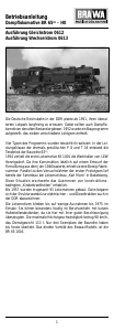
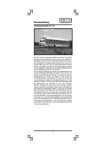
Operating instructions
diesel locomotive V 100 – N
After the war, the East German State Railways
started a diesel locomotive programme in order
to swiftly replace the steam locomotives which
still operated in large numbers. The medium
power class was to be covered with a locomotive
model with central driver’s cab and an engine
output ranging between 480 kW and 880 kW
(650 to 1200 PS). This model was eventually
realized as V 100. In close cooperation with the
Institute for Rail Cars, the former nationally-
owned locomotive construction works “Karl
Marx” in Babelsberg developed the basic design
as from 1963 und afterwards manufactured the
design locomotives. The first 40 series
locomotives with an engine output of 736 kW
were delivered to the German Democratic
Republic in 1966/67. In 1970, the locomotives V
100 001 to V 100 171 were renamed 110 001 to
110 171. During the years 1970 to 1978, the series
locomotives 110 202 to 110 896 were built for
the East German State Railways at the engine
works Henningsdorf. In 1981, after lengthy trials,
some locomotives received an output of 883 kW
(1200 PS), as from 1983 even of 1100 kW (1500
PS).
The machines which had thus gained strength
received the new series designation 112 and 114,
retaining the old key number. Since the 1
st
of
January 1992, the BR 110 carries the new series
designation 201. The 112 and the 114 turned
into the 202 and 204. In total, 865 locomotives
of the 110 series left the workshops in Hennings-
dorf.
2 3 4 5 6 7 8
Inhaltsverzeichnis
Contents
Benennung Seite
Allgemeine Hinweise ....................................... 5
Wartungsarbeiten
• 1. Gehäuse demontieren ........................... 6
• 2. Motor tauschen ..................................... 6
• 3. Platinen tauschen,
Glühbirne wechseln ............................... 6
• 4. Drehgestell ausbauen,
Haftreifen erneuern,
Kupplung tauschen ................................ 6
• 5. Ölen ....................................................... 9
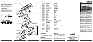
Ersatzteilliste ........................................ 10 – 13
Bestellbeispiel ............................................... 12
Description Page
General information ........................................ 5
Maintenance works
• 1. Dismantling the housing ........................ 8
• 2. Exchanging the motor ........................... 8
• 3. Exchanging circuit board,
changing bulb ........................................ 8
• 4. Removing the bogie,
renewing the traction tires,
exchanging the coupling ....................... 8
• 5. Lubricating ............................................ 9
Spare parts list ..................................... 10 – 13
Order example ............................................... 13
Allgemeine Montage- und
Sicherheitshinweise
• Diese Bedienungsanleitung beschreibt
sämtliche Arbeitsvorgänge die zur Wartung
und Instandhaltung notwendig sind. Bitte
lesen Sie diese Bedienungsanleitung bevor
Sie mit den Arbeiten beginnen.
• Bei unsachgemäßem Umgang mit elektri-
schen Bauteilen können diese zerstört
werden. Für entsprechende Arbeiten (z.B.
Platinenwechsel) können Sie sich an Ihren
Fachhändler oder den Hersteller wenden.
• Bei den folgenden Wartungsarbeiten ist die
jeweilige Demontage beschrieben, der
Zusammenbau ist in umgekehrter
Reihenfolge auszuführen.
• Achten Sie beim Zerlegen der Lokomotive
auf die Einbaulage der entsprechenden
Bauteile. Wird ein Bauteil falsch eingebaut
kann dieses zerstört werden oder es kommt
zu Funktionsstörungen im Betrieb.
• Jegliche Kabel oder Verbindungsdrähte die in
diesem Produkt verbaut sind dürfen nicht in
eine Netzsteckdose eingeführt werden.
Lebensgefahr!
General assembly and safety
information
• These operating instructions describe all
work steps necessary for maintenance and
repair. Please read these operating
instructions carefully before you start with
your work.
• In the case of incorrect handling of electrical
components, they may be destroyed. Please
ask your specialist dealer to help with the
necessary work (e.g. changing circuit
boards).
• In the case of maintenance work, the
disassembly is described below, to re-
assemble the tractor reverse the work steps.
• When dismantling the engine make a note
of the mounted position of the individual
parts. An incorrectly mounted part can be
destroyed or operation can be disrupted.
• All cables and connection wires installed in
this product may not be inserted in a mains
socket. Danger!
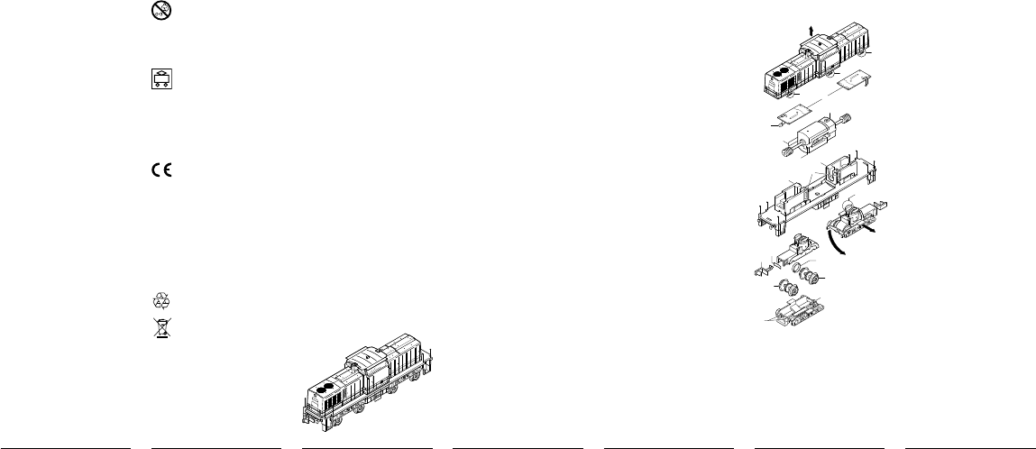
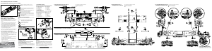
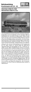
Wartungsarbeiten
1. Gehäuse demontieren (Fig. 1)
Gehäuse (1) leicht zusammendrücken, Snap-in
(2) ausclipsen und nach oben abnehmen.
2. Motor tauschen (Fig. 1)
Gehäuse demontieren, siehe Punkt 1.
Kontaktbleche (3) aus der Kontaktbrücke am
Gewicht (4) herausziehen, Motor (5) mit Schnek-
ken nach oben herausziehen.
Achtung:
Auf richtige Einbaulage des Motors achten.
3. Platinen tauschen, Glühbirne wechseln
(Fig. 1)
Gehäuse demontieren, siehe Punkt 1.
Platinen (6) im inneren des Gehäuses vorsichtig
aus den Sicherungszapfen (4 Stück je Platine)
herausziehen, Glühbirne (7) ablöten.
4. Drehgestell ausbauen, Haftreifen
erneuern, Kupplung tauschen (Fig. 1)
– Drehgestell ausbauen
Drehgestell (8) vorsichtig nach rechts
(zur Seite A) drücken und nach unten (B) aus-
clipsen.
– Haftreifen erneuern, Kupplung tauschen
Drehgestell ausbauen:
Drehgestell (8) vorsichtig nach rechts
(zur Seite A) drücken und nach unten (B) aus-
clipsen.
Snap-in (9) lösen und Drehgestell umdrehen,
Räder müssen nach oben zeigen. Rahmen (10)
abnehmen, jetzt sind die Räder (11) frei zugäng-
lich und die Haftreifen (12) können erneuert
werden. Kupplung (13) entnehmen.
Beim Zusammenbau ist auf den richtigen Sitz
der Kupplungsfeder (14) zu achten.
4
1
2
2
2
6
3
5
7
3
8
A
B
Clip
4
4
9
9
10
12
11
11
13
14
Fig. 1
Maintenance works
1. Dismantling the housing (Fig. 1)
Squeeze housing together lightly, clip out
the snap-in (2) and remove upwards.
2. Exchanging the motor (Fig. 1)
Dismantle housing, see item 1.
Pull out the contact plate from the contact bridge
on the weight, pull out the motor (5) and worm
gear upwards.
Warning:
Ensure that the motor is in the correct
installation position.
3. Exchanging circuit-board, changing
bulb (Fig. 1)
Dismantle housing, see item 1.
Carefully remove the circuit board (6) within the
housing from the securing clips (4) on each circuit
board, unsolder bulb (7).
4. Removing the bogie, renewing the
traction tires, exchanging the coupling
(Fig. 1)
– Removing the bogie
Carefully press the bogie (8) to the right
(to side A) and unclip downwards (B).
– Renewing the traction tires, exchanging
the coupling
Remove bogie:
Carefully press the bogie (8) to the right
(to side A) and unclip downwards (B).
Release the snap-in (9) and turn the bogie
over, the wheels must face upwards.
Remove frame (10), now the wheels are
freely accessible so that the traction tires (12)
can be renewed. Remove coupling (13).
Take care that the coupling spring (14) is in
the right position when assembling.
Nicht bestimmt für Kinder unter 3
Jahren. Verschluckbare Kleinteile.
Betriebsanleitung aufbewahren!
Not recommended for children under
3 years of age. Small parts may be
swallowed. Retain the operating
instructions!
Zum Betrieb des vorliegenden
Produkts darf als Spannungsquelle
nur ein nach VDE 0551/EN 60742
gefertigter Spielzeug-Transformator
verwendet werden.
Only a toy transformer produced
compliant with VDE 0551/EN 60742
may be used as a voltage source to
operate this product.
Dieses Produkt entspricht den
grundlegenden Sicherheits- und
Gesundheitsanforderungen der
Europäischen Richtlinie für
Spielzeuge (88/378/EWG) unter
Beachtung der Europäischen
Sicherheitsnorm EN 71.
This product conforms to the
fundamental health and safety
requirements of the European
Directive for Toys (88/378/EEC) with
due regard to the European Safety
Standard EN 71.
Elektro- und Elektronikaltgeräte dürfen
nicht in den Hausmüll gelangen. Sie
müssen entsprechend der jeweils
gültigen Länderrichtlinien fachgerecht
entsorgt werden.
Electrical equipment may not reach to
domestic waste. According to the
current terms of the country reference
the electrical eqipment must
professional disposed.

Praat mee over dit product
Laat hier weten wat jij vindt van de Brawa 61102 V 100 (N) Modeltrein. Als je een vraag hebt, lees dan eerst zorgvuldig de handleiding door. Een handleiding aanvragen kan via ons contactformulier.