
Alu szúnyoghálós ajtó
Bevezető
Szívből gratulálunk! Vásárlásával minőségi termék
mellett döntött. Szerelés előtt ismerje meg a termé-
ket. Ehhez olvassa el figyelmesen a következő sze-
relési utasítást és a biztonsági előírásokat. A terméket csak a
leírtak szerint és a megadott felhasználási területeken alkal-
mazza. Ezt az utasítást jól őrizze meg. A termék harmadik
személynek történő továbbadása esetén adja át a teljes
termékdokumentációt is.
Rendeltetésszerű használat
A termék a legyekhez hasonló rovarokkal szembeni védelemre
szolgál a lakásban. Az előbb leírttól eltérő alkalmazás vagy
a termék megváltoztatása nem engedélyezett és sérülésekhez
és / vagy a termék megkárosodásához vezethet. A rendelete-
tésétől eltérő használatból eredő károkért a gyártó nem felel.
A terméket nem közületi felhasználásra szánták.
Alkatrészleírás és a csomag tartalma
Tudnivaló: a kicsomagolásnál ügyeljen arra, hogy az
alkatrészek valamelyikét nehogy kidobja. A kicsomagolás után
azonnal ellenőrizze a csomagolás tartalmát, annak teljességét,
valamint a termék és az elemek kifogástalan állapotát. Semmi
esetre se szerelje fel a terméket, ha a szállítmány nem teljes.
A
2 Sarokösszekötő
B
2 alumínium profil (2060 mm)
C
1 alumínium profil 940 mm
D
1 Középlemez 940 mm
E
1 alumínium-padlólemez 940 mm
F1
1 kefetömítés 15 mm vastag
F2
1 kefetömítés 5 mm vastag
G1
2 rögzítőléc, hosszú
G2
4 rögzítőléc, rövid
H
3 zsanér felsőrész
I
3 zsanér alsórész
J
3 zsanérfedél
K
3 rugó
L
2 zárólemez
M
4 süllyesztettfejű csavar zárólemezekhez
N
2 mágnes
Producent / Serwis
Smartmaxx GmbH
Inselstraße 27
D-04103 Lipsk
Infolinia: +49 (0) 341 99 99 43 79
IAN 43011
Przed skontaktowaniem się z działem serwisowym należy
przygotować paragon i numer artykułu (np. IAN 12345)
jako dowód zakupu.
Montaż ramy bez mechanizmu
samozamykającego
Przy tym wariancie nie wymagane są żadne sprężyny zamy-
kające
K
.
Krok 1
Za pomocą szczypiec odciąć końcówki dolnych części zawiasu
I
aż do końca nacięcia (patrz rys. 17).
Wskazówka: Wżadnym wypadku nie należy odcinać
całej części. Wprzeciwnym wypadku zawias nie będzie
nadawał się do użytku.
Krok 2
Włożyć dolne części zawiasu
I
w górne części zawiasu
H
.
Postąpić zgodnie z krokami 3 do 6 rozdziału „Montaż ramy
z mechanizmem samozamykającym” (bez zastosowania
sprężyn
K
).
Czyszczenie i pielęgnacja
W żadnym wypadku nie używaj żrących ani szorujących
środków czyszczących.
Ramę należy czyścić lekko zwilżoną, nie strzępiącą się
ścierką.
W razie potrzeby należy użyć łagodnego środka czysz-
czącego.
Utylizacja
Opakowanie wykonane jest z materiałów przyja-
znych dla środowiska naturalnego. Należy wyrzu-
cać je do lokalnych pojemników recyklingowych.
Informacje o możliwościach dotyczących wyrzucania otrzymać
można w urzędzie miejskim lub gminnym.
Film montażowy
www.smartmaxx.info
Montaż ramy z mechanizmem
samozamykającym
Krok 1
Rozłożyć górne części zawiasów
H
równomiernie na profilu
B
naprzeciw strony uchwytów. Zwracać przy tym uwagę,
aby pozostawić odstęp pomiędzy górną i dolną krawędzią
ramy a górną częścią zawiasu
H
wynosił co najmniej 15 cm.
Używając wiertła 2,0 mm przewiercić otwory (patrz rys. 12).
Krok 2
Górne części zawiasów
H
przymocować śrubami
Q
naj-
pierw na dolnym otworze w profilu aluminiowym
B
ramy
siatki ochronnej. Sprężyny
K
wsunąć do góry w górne
części zawiasów
H
i przykręcić je śrubami
Q
na górnym
otworze (patrz rys. 12).
Krok 3
Drzwi chroniące przed owadami należy dostawić do oścież-
nicy. Wrazie potrzeby wtrakcie tej czynności należy skorzy-
stać zpomocy drugiej osoby. Stronę drzwi chroniących przed
owadami, po której zamontowane są magnesy
N
(strona z
uchwytem) należy ustawić przy ościeżnicy w taki sposób,
aby ok. 2,5 cm profilu podłużnego
B
drzwi chroniących
przed owadami nachodziło na ościeżnicę. W ten sposób
wykorzystać można optymalną siłę zamykania magnesów
N
(zobacz rys. 13).
Krok 4
Założyć dolne części zawiasu
I
przez sprężyny
K
na
górne części zawiasu
H
. Dolne części zawiasu
I
przyłożyć
do ościeżnicy i oznakować miejsca na otwory 2 i 4 (patrz
rys. 14).
Krok 5
Używając wiertła 2,0 mm, wywiercić otwory i przykręcić
dolne części zawiasu
I
każdorazowo za pomocą dwóch
śrub z łbem wpuszczanym
Q
ościeżnicy. Unieruchomić sprę-
żyny
K
i w tym celu należy nałożyć zaślepki zawiasów
J
na dolne części zawiasów
I
(patrz rys. 15).
Krok 6
Przymocować płyty zamykające
L
każdorazowo za pomocą
dwóch śrub z łbem wpuszczanym
M
do ościeżnicy na wyso-
kości magnesów
N
(patrz rys. 16).
Także pozostawić wystające 3 cm i obciąć uszczelkę szczot-
kową
F2
(patrz rys. 8).
Krok 9
Na wymieniony w kroku 8 profil aluminiowy
B
wetknąć
profil poprzeczny
D
na łącznik profilu poprzecznego
V1
.
Uwaga: Nawiercony wcześniej koniec musi leżeć po stronie
magnesu (rys. 8).
Krok 10
Dokończyć montaż ramy, nakładając drugi profil aluminiowy
B
na wolne końce profilu aluminiowego
C
i profilu poprzecz-
nego
D
oraz przykręcając do aluminiowej płyty ochronnej
E
przy pomocy śrub Trox
P1
. Do wbicia łącznika narożnego
A
zastosować ewentualnie gumowy młotek (patrz rys. 8).
Krok 11
Pociąć długie listwy typu click
G1
na cztery części, odpowied-
nie dla górnego idolnego obszaru profili aluminiowych
B
.
Skrócić cztery listwy typu click
G2
na zmierzoną szerokość
B
minus 2 cm (patrz rys. 9).
Krok 12
Nałożyć tkaninę z włókna szklanego
S
na ramę. Napiąć
najpierw górną połowę siatki ochronnej. Przyczepianie tka-
niny z włókna szklanego
S
za pomocą listwy typu click
G
do profilu aluminiowego
C
rozpocząć od górnego lewego
lub górnego prawego rogu. Czynność tę kontynuować z
listwą typu click
G
na profilu poprzecznym
D
. Przymoco-
wać teraz przy pomocy listwy typu click
G
tkaninę z włókna
szklanego
S
do górnej połowy ramy po lewej i prawej stro-
nie w profile aluminiowe
B
(patrz rys. 10).
Krok 13
Tkaninę z włókna szklanego
S
przyciąć szczelnie przy listwie
typu click
G
profilu poprzecznego
D
. Usunąć wystającą
tkaninę za pomocą noża introligatorskiego (patrz rys. 10).
Należy wziąć pozostałą tkaninę z włókna szklanego
S
i
postąpić z dolną częścią ramy ochronnej jak z górną częścią
w kroku 12 (patrz rys. 10).
Krok 14
Uchwyt zewnętrzny
U1
wetknąć z kanałem śrubowym w
wywiercony otwór profilu poprzecznego
D
i przymocować
go przez przykręcenie uchwytu środkowego
U2
z tyłu (patrz
rys. 11).
Krok 4
Wsunąć każdy profil aluminiowy
B
na już nawierconym
końcu pasującego łącznika narożnego płyty ochronnej
T1
i
T2
w otwór profilu.
Uwaga: Do łącznika narożnego położonego po stronie
przeciwnej względem późniejszej strony z zawiasem należy
włożyć magnes
N
(rys. 4). W razie potrzeby do wbicia
łączników narożnych
T1
i
T2
użyć ewentualnie gumowego
młotka. W profil aluminiowy
B
wsunąć od góry uszczelkę
szczotkową
F2
w przeznaczony na to wpust aż do dołu do
założonego wcześniej łącznika narożnego
T1
i
T2
. U góry
pozostawić wystające 3 cm i obciąć uszczelkę szczotkową
F2
(patrz szczegółowy rys. 4). Te same czynności wykonać
na drugim profilu aluminiowym
B
.
Krok 5
Profil aluminiowy
B
przykręcić do płyty ochronnej
E
przy
pomocy śrub Torx
P1
i bitu Torx
P2
(patrz rys. 5). Uszczelkę
szczotkową
F2
wsunąć w aluminiowej płycie ochronnej
E
w przewidziany na to wpust aż do łącznika narożnego
T1
względnie
T2
i obciąć ją z odstępem wynoszącym 3 cm.
Uszczelkę szczotkową
F1
na dolnej stronie płyty ochronnej
E
wsunąć w przewidziany na to wpust i obciąć ponownie z
odstępem wynoszącym 3 cm (rys. 5).
Krok 6
W profilu aluminiowym
B
wsunąć od góry łącznik profilu
poprzecznego
V1
w przewidziany do tego wpust (patrz rys.
6 / a). Łączniki narożne
A
włożyć przy uwzględnieniu
uszczelki szczotkowej u góry w profile aluminiowe
B
.
Uważać przy tym, aby, włożyć w łącznik narożny
A
, który
później będzie leżał po przeciwnej stronie zawiasu, drugi
magnes
N
(patrz rys 6 / b).
Krok 7
W środkowej części obu profili aluminiowych
B
ustalić
położenie łączników profilu poprzecznego
V1
i oznaczyć
ołówkiem miejsca do wiercenia. Wywiercić tam przy pomocy
2,0 mm wiertła po jednym otworze na środkowej stronie
profilu. Przymocować łącznik profilu poprzecznego
V1
przy
pomocy śruby
V2
przez wywiercony otwór w profilu alumi-
niowym
B
(patrz rys. 7).
Krok 8
Profil aluminiowy
C
wetknąć na łącznik narożny
a
już
zamontowanego do płyty ochronnej
E
profilu aluminiowego
B
. Opatrzyć profil aluminiowy
C
pozostałą uszczelką
szczotkową
F2
i przesunąć ją aż do łącznika narożnego
A
.
Montaż
Przed montażem należy upewnić się, że drzwi przystoso-
wane są do tego produktu. Należy sprawdzić czy oścież-
nica drzwi nie przekracza maksymalnego wymiaru.
OSTROŻNIE NIEBEZPIECZEŃSTWO URAZU! Do
montażu potrzebna jest piła do metalu, nóż introligatorski
oraz wiertarka elektryczna. Należy koniecznie przestrze-
gać instrukcji obsługi zastosowanych narzędzi oraz
stosować rękawice ochronne.
Montaż ramy
Krok 1
Należy dokonać pomiaru wymiarów wewnętrznych (H =
wysokość, B. = szerokość) ościeżnicy (rys. 1). Należy uważać
na dostępną dodatkową powierzchnię na ościeżnicy po każ-
dej stronie wynoszącą 30 mm. Jeśli nie ma tej powierzchni to
należy indywidulanie dopasować wymiary każdorazowo po
2 cm przy uwzględnieniu zawiasów i magnesów. Dodać do
wymierzanej wysokości H 0,5 cm i do otrzymanego wymiaru
skrócić profile aluminiowe
B
przy pomocy piły do metalu i
korytka do cięcia pod kątem (rys. 1). Od zmierzonej szeroko-
ści B odjąć 2 cm. Przy pomocy piły do metalu należy skrócić
profil aluminiowy
C
, profil poprzeczny
D
i aluminiową płytę
ochronną
E
do ustalonego wymiaru (rys. 1). Obcięte kra-
wędzie należy opiłować.
Krok 2
Nałożyć szablon do wiercenia otworu
O
na koniec profilu
aluminiowego
B
i wsunąć go do oporu. Wywiercić wiertłem
4 mm otwór na śrubę z pomocą bocznych otworów na
szablonie
O
przez ścianki profilu (rys. 3a). Powtórzyć ten
proces przy drugim profilu aluminiowym
B
.
Uwaga: Nałożyć tutaj wywiercone otwory na przeciwnym
końcu, tak aby boki profili aluminiowych
B
z wierceniami
leżały odwrócone do siebie.
Krok 3
Nałożyć szablon do wiercenia otworu
O
na koniec profilu
poprzecznego
D
i wsunąć go do oporu. Z pomocą kanału
wiercenia B na wierzchniej stronie szablonu
O
wywiercić
otwór szablonu w profilu
D
(ø 6,0 mm).
J
3 zaślepki zawiasów
K
3 sprężyny
L
2 płyty zamykające
M
4 śruby z łbem wpuszczanym do płyt zamykających
N
2 magnesy
O
1 szablon do wiercenia otworów
P1
4 śruby Torx 50 mm
P2
1 bit Torx do śrub Torx
Q
9 śrub z łbem wpuszczanym 25 mm
R
3 śruby z łbem wpuszczanym 16 mm
S
1 tkanina z włókna szklanego
T1
1 łącznik narożny płyty ochronnej, lewy
T2
1 łącznik narożny płyty ochronnej, prawy
U1
1 uchwyt zewnętrzny
U2
1 uchwyt wewnętrzny
V1
2 łączniki profili
V2
2 śruby łączników profili
1 instrukcja montażu
Dane techniczne
Maks. wymiar zestawu: 100 x 210 cm
Maks. wymiar wewnętrzny ościeżnicy: 94 x 204 cm
Wskazówki bezpieczeństwa
NIEBEZPIECZEŃ-
STWO UTRATY ŻYCIA LUB ODNIESIE-
NIA OBRAŻEŃ PRZEZ DZIECI! Nigdy nie
należy pozostawiać dzieci zmateriałem opakowaniowym
oraz produktem bez nadzoru. Istnieje niebezpieczeństwo
uduszenia się materiałem opakowania i niebezpieczeń-
stwo utraty życia wskutek udławienia się. Dzieci często
nie dostrzegają niebezpieczeństwa. Dzieci nie powinny
mieć dostępu do produktu. Produkt nie jest zabawką.
OSTROŻNIE! NIEBEZPIECZEŃSTWO URAZU!
Należy upewnić się, że wszystkie części zostały zamon-
towane w należyty sposób oraz że nie są uszkodzone.
Nieprawidłowy montaż grozi niebezpieczeństwem urazu.
Uszkodzone elementy mogą obniżać bezpieczeństwo i
pogarszać funkcjonowanie.
HU PLPLPLPLPLPLPL
8
B
P1
B
C
D
E
V1
O
1 šablona za vrtanje
P1
4 torx vijaki 50 mm
P2
1 torx nastavek za torx vijake
Q
9 vijakov z ugreznjeno glavo 25 mm
R
3 vijaki z ugreznjeno glavo 16 mm
S
1 tkanina iz steklenih vlaken
T1
1 kotni spojnik pohodne pločevine levo
T2
1 kotni spojnik pohodne pločevine desno
U1
1 zunanji ročaj
U2
1 notranji ročaj
V1
2 spojnika za prečke
V2
2 vijaka spojnikov za prečke
1 navodilo za montažo
Tehnični podatki
Največja dimenzija kompleta: 100 x 210 cm
Največja notranja dimenzija
vratnega okvirja: 94 x 204 cm
Varnostni napotki
SMRTNA NEVAR-
NOST IN NEVARNOST NESREČ ZA
MALČKE IN OTROKE! Otrok z embalažnim
materialom in izdelkom nikoli ne pustite nenadzorovanih.
Obstaja nevarnost zadušitve zaradi embalažnega
materiala in smrtna nevarnost zaradi zadavitve. Otroci
pogosto podcenjujejo nevarnosti. Otrokom nikoli ne dovo-
lite zadrževanja v bližini izdelka. Ta izdelek ni igrača.
POZOR! NEVARNOST TELESNIH POŠKODB! Pre-
pričajte se, ali so vsi deli nepoškodovani in pravilno mon-
tirani. V primeru nestrokovne montaže obstaja nevarnost
poškodb. Poškodovani deli lahko negativno vplivajo na
varnost in delovanje.
Montaža
Pred montažo preverite, ali so vaša vrata primerna za ta
izdelek. Preverite tudi, ali mere vašega vratnega okvirja
ne presegajo največje mere.
POZOR, NEVARNOST TELESNIH POŠKODB! Za
montažo potrebujete žago za železo, olfa nož in vrtalni
stroj. Obvezno upoštevajte navodila za uporabo orodij,
ki jih potrebujete, in nosite zaščitne rokavice.
SIHU HU HU HU HU HU SI
Aluminijasta vratna zaščita pred mrčesom
Uvod
Iskrene čestitke! Z nakupom ste se odločili za
kakovosten izdelek. Pred montažo se seznanite z
izdelkom. V ta namen natančno preberite spodnje
navodilo za montažo in varnostne napotke. Izdelek uporabljajte
samo tako, kot je opisano, in samo za predviden namen upo-
rabe. Navodila skrbno shranite. V primeru izročitve izdelka
tretjim, jim predajte tudi vso dokumentacijo.
Predvidena uporaba
Ta izdelek je predviden za zaščito pred mrčesom in muhami
v zasebnih stanovanjskih prostorih. Kakršna koli drugačna
uporaba od zgoraj opisane ali spreminjanje izdelka ni dovo-
ljeno in lahko povzroči telesne poškodbe in / ali poškodbe
izdelka. Za poškodbe, nastale zaradi nepredvidene uporabe,
proizvajalec ne prevzema odgovornosti. Izdelek ni predviden
za poslovno uporabo.
Opis delov in obseg dobave
Napotek: Pri razpakiranju pazite na to, da pomotoma na
odvržete stran montažnega materiala. Takoj ko odvijete
embalažo, preverite popolnost in nepoškodovanost izdelka
ter vseh delov. Izdelka nikoli ne montirajte, če obseg dobave
ni popoln.
A
2 kotna spojnika
B
2 aluminijasta profila 2060 mm
C
1 aluminijasti profil 940 mm
D
1 srednja prečka 940 mm
E
1 aluminijasta pohodna pločevina 940 mm
F1
1 krtačno tesnilo debeline 15 mm
F2
1 krtačno tesnilo debeline 5 mm
G1
2 dolgi zaskočni letvi
G2
4 kratke zaskočne letve
H
3 zgornji deli tečaja
I
3 spodnji deli tečaja
J
3 pokrivne kapice tečaja
K
3 vzmeti
L
2 zaporni plošči
M
4 vijaki z ugreznjeno glavo za zaporne plošče
N
2 magneta
Ártalmatlanítás
A csomagolás környezetbarát anyagokból áll. A
helyi újrahasznosítási tartályokba helyezve semmi-
sítse meg ezeket.
A kiszolgált termék megsemmisítésének lehetőségeiről tájéko-
zódjon a községi vagy városi önkormányzatnál.
Szerelési videó
www.smartmaxx.info
Gyártó / szerviz
Smartmaxx GmbH
Inselstraße 27
D-04103 Leipzig
Hotline: +49 (0) 341 99 99 43 79
IAN 43011
Kérjük, kérdések esetére készítse elő a pénztárblokkot és a
cikkszámot (pl. IAN 12345) a vásárlás tényének az igazo-
lására.
4. lépés
Most helyezze a zsanér alsó részeket
I
a rugókon
K
keresztül
a zsanér felsőrészekbe
H
. Tartsa a zsanér alsó részeket
I
az ajtótokhoz és jelölje meg a 2. és 4. lyukak helyét (lásd a
14. ábrát).
5. lépés
Fúrja ki a lyukakat egy 2,0 mm-es fúróval és csavarozza a
zsanér alsórészeket
I
egyenként két-két süllyesztettfejű csa-
varral
Q
az ajtótokhoz. Rögzítse a rugót
K
úgy, hogy a
zsanérfedelet
J
a zsanér- alsó részre
I
helyezi (lásd a
15. ábrát).
6. lépés
Rögzítse a zárólemezeket
L
két-két süllyesztettfejű csavarral
M
az ajtótokra a mágnesek
N
magasságában (lásd a 16.
ábrát).
Az önzáródó funkció nélküli
keret szerelése
Ennél a változatnál nincsen szükség zárórugókra
K
.
1. lépés
Csípje le a rovátkák végéig a zsanér alsórészek
I
csúcsait
(lásd az 17. ábrát).
Tudnivaló: semmi esetre se csípje le a teljes hídrészt. Ellen-
kező esetben a zsanér használhatatlanná válik.
2. lépés
Helyezze a zsanér alsó részeket
I
a zsanér felsőrészekbe
H
. Kövesse „A keretnek az önzáró mechanizmussal történő
felszerelése“ c. fejezet 3 - 6. munkaelemét (rugók
K
haszná-
lata nélkül).
Tisztítás és ápolás
Semmiképpen ne használjon maró, vagy súroló hatású
tisztítószereket.
Tisztítsa a keretet egy szöszmentes, enyhén megnedvesí-
tett kendővel.
Esetleg használjon erre a célra enyhe tisztítószert.
12. lépés
Helyezze az üvegszálszövetet
S
a keretre. Először a szú-
nyogháló- keret felső részét feszítse fel. Kezdje ehhez az
üvegszálszövetet
S
a bepattanó-léc
G
segítségével rögzí-
teni az alumínium profilba
C
felül a bal, vagy a jobb szélnél.
Folytassa ezt az eljárást a bepattanó-léc
G
segítségével a
középlemezen
D
. Rögzítse a bepattanó-lécekkel
G
az
üvegszálszövetet
S
a keret felső részébe balra és jobbra az
alumínium-profilokban
B
(lásd a 10. ábrát).
13. lépés
Vágja ki az üvegszálszövetet
S
szorosan a középlemez
D
bepattanó-lécére
G
. Távolítsa el a felesleges szövetet a
szőnyegvágó késsel (lásd az 10. ábrát). Vegye a maradék
üvegszálszövetet
S
és a szúnyoghálókeret alsó részével a
felső résznél a 12. lépésben leírtak szerint járjon el (lásd a
10. ábrát).
14. lépés
Dugja be a külső fogantyút
U1
a csavarcsatornával a közép-
lemezen
D
előfúrt lyukon és rögzítse ezeket úgy, hogy a
belső fogantyút
U2
hátulról ellencsavarozza (lásd a 11. ábrát).
Az önzáródó keret szerelése
1. lépés
Egyenletesen ossza el a zsanér- felsőrészeket
H
a profilon
B
a fogantyúval szemben. Ügyeljen arra, hogy a keret felső-
és alsó pereme és a zsanér felsőrész
H
közötti távolság
minimum 15 cm legyen. Fúrja ki a lyukakat egy 2,0 mm-es
fúróval (lásd a 12. ábrát).
2. lépés
Először a szúnyoghálós ajtókeret alumíniumprofiljának
B
alsó furatán keresztül rögzítse a csavarral
Q
a zsanér- felső-
részeket
H
. Ezután tolja fel a rugókat
K
a zsanér felsőré-
szekbe
H
és rögzítse azokat a csavarokkal
Q
a felső furaton
keresztül (lásd a 12. ábrát).
3. lépés
Helyezze a rovarvédő-ajtót az ajtótokhoz. Ennél a műveletnél
esetleg vegye igénybe egy másik személy segítségét. Igazítsa
a szúnyoghálós ajtónak azt az oldalát, amelybe a mágnesek
N
vannak beszerelve (a fogantyús oldalon) úgy az ajtótokhoz,
hogy kb. 2,5 cm a hosszanti profilból
B
az ajtótokra felfe-
küdjön. Ezáltal kihasználhatja a mágnesek
N
optimális
záróerejét (lásd az 13. ábrát).
F2
az alumínium-padlólemez
E
erre a célra szolgáló hor-
nyába egészen a sarokösszekötőig
T1
, ill.
T2
és vágja le azt
kb. 3 cm-es ráhagyással. Tolja be a kefetömítést
F1
a padló-
lemez
E
alsó oldalán lévő horonyba és vágja le azt kb.
3 cm-es ráhagyással (5. ábra).
6. lépés
Tolja az alumíniumprofilt
B
fentről egy középlemez- össze-
kötővel
V1
az erre a célra szolgáló horonyba (lásd a 6 / a
ábrát). Helyezze a sarokösszekötőt
A
a kilógó kefetömítéssel
együtt felülről az alumínium profilba
B
. Ügyeljen arra, hogy
a majdani zsanéroldallal szemközti sarokösszekötőbe
A
helyezze a második mágnest
N
(lásd a 6 / b ábrát).
7. lépés
Határozza meg mindkét alumínium profil
B
középhelyzetét
a középlemez-összekötőn
V1
és jelölje meg a furatpontokat
egy tollal. Fúrjon oda egy-egy lyukat a profil belső oldalába
egy 2,0 mm-es fúróval. Rögzítse a középlemez- összekötőt
V1
egy csavarral
V2
a korábban kifúrt lyukon keresztül az
alumíniumprofilba (lásd a 7. ábrát).
8. lépés
Tolja az alumíniumprofilt
C
a már a padlólemezhez
E
sze-
relt alumíniumprofil
B
sarokösszekötőjére
A
. Használja fel
az alumínium profilhoz
C
a maradék kefetömítést
F2
és tolja
át azt egészen a sarokösszekötőig
A
. A felső végen most is
hagyjon rá 3 cm kefetömítést
F2
(lásd a 8. ábrát).
9. lépés
Dugja a 8. lépésben említett alumínium profilra
B
a közép-
lemezt
D
a középlemez-összekötőn
V1
.
Figyelem: Az előfúrt véget a mágneses oldalra kell fektetni
(8. ábra).
10. lépés
Fejezze be a keretet úgy, hogy a második alumínium profilt
B
rádugja a
C
alumínium profil és a középlemez
D
sza-
bad végeire és a trox- csavarokkal
P1
összecsavarozza az
alumínium-padlólemezzel
E
. Adott esetben használjon
gumikalapácsot a sarokösszekötők
A
beütéséhez (lásd a 8.
ábrát).
11. lépés
Vágja négy részre a hosszú bepattanó-lécet
G1
úgy, hogy az
illeszkedjen az alumínium profil
B
felső és alsó részéhez.
Rövidítse le a négy bepattanó-lécet
G2
a mért szélességnél
B
2 cm-rel rövidebbre (lásd a 9. ábrát).
A keret összeszerelése
1. lépés
Mérje meg előbb az ajtótok méreteit (H = magasság, B =
szélesség) (1. ábra). Ügyeljen arra, hogy minden oldalon
meglegyen a 30 mm-es felület az ajtótok felfektetéséhez. Ha
nem adott ez a felület, akkor alakítsa egyénileg a méretet, de
vegye figyelembe, hogy a zsanér és a mágnes számára
maradjon 2-2 cm. Adjon a mért magassághoz H 0,5 cm-t és
rövidítse meg az alumínium profilokat
B
egy fűrész és egy
fűrészláda segítségével a megállapított méretre (1. ábra).
Vonjon le a mért szélességből B 2 cm-ert. Rövidítse meg az
alumínium profilt
C
, a középső elosztót
D
és az alumínium-
küszöblemezt
E
a mért méretre (1. ábra). Sorjázza le a
vágási felületet.
2. lépés
Tegye a fúrósablont
O
az alumíniumprofil
B
egyik végére
és tolja azt ütközésig. Egy 4 mm-es fúróval a sablon
O
oldalsó
furatainak segítségével fúrja át a profilfalat (3a. ábra). Ismé-
telje meg a folyamatot a második alumínium profilon
B
is.
Figyelem: Helyezze ide az ellentétes végen található fura-
tokat úgy, hogy az alumíniumprofilok
B
furattal ellátott
végei tükörfordításban legyenek egymáshoz képest.
3. lépés
Tegye a fúrósablont
O
a középrész
D
egyik végére és tolja
azt ütközésig. A fúrócsatorna B segítségével fúrja a sablon
O
felső részére a csavarlyukat a profilon
D
keresztül (ø 6,0 mm).
4. lépés
Ezután tolja az alumíniumprofil
B
előfúrt végét a hozzá
passzoló sarokösszekötő padlólemezhez
T1
és
T2
a profil-
nyílásba.
Figyelem: helyezzen a majdani zsanéroldallal szemközti
sarokösszekötőbe egy mágnest
N
(lásd a 4. ábrát). Adott
esetben a sarokösszekötők
T1
és
T2
behelyezéséhez hasz-
náljon gumikalapácsot. Tolja be felülről az alumínium profilba
B
a kefetömítést
F2
, az erre a célra szolgáló horonyba,
egészen az alul már elhelyezett sarokösszekötőig
T1
és
T2
.
A felső végen hagyjon 3 cm-t túllógni, majd vágja le a felesle-
ges kefetömítést
F2
(lásd a 4 ábra részletképét). A második
alumínium profillal
B
ugyanígy járjon el.
5. lépés
Csavarozzon össze egy alumíniumprofilt
B
az alumínium-
padlólemezzel
E
egy torx- csavar
P1
és egy torx- feltét
P2
segítségével (lásd az 5. ábrát). Ezután tolja be a kefetömítést
O
1 fúrósablon
P1
4 torxcsavar 50 mm
P2
1 torx-csavarhúzófej torxcsavarhoz
Q
9 süllyesztettfejű csavar 25 mm
R
3 süllyesztettfejű csavar 16 mm
S
1 üvegszál-szövet
T1
1 sarokösszekötő padlólemez bal
T2
1 sarokösszekötő padlólemez jobb
U1
1 külső fogantyú
U2
1 belső fogantyú
V1
2 elosztó- összekötő
V2
2 csavaros elosztó-összekötő
1 szerelési útmutató
Műszaki adatok
Max. beépítési méret: 100 x 210 cm
Az ajtótok max. belmérete: 94 x 204 cm
Biztonsági tudnivalók
KISGYEREKEK ÉS
GYEREKEK SZÁMÁRA ÉLET- ÉS BAL-
ESETVESZÉLYES! Soha NE hagyja a gyere-
keket felügyelet nélkül a csomagolóanyagokkal és a
termékkel. A csomagolóanyagok által fulladásveszély és
megfojtás általi életveszély fenyeget. A gyerekek gyakran
alábecsülik a veszélyeket. Tartsa a gyerekeket mindig
távol a terméktől. A termék nem játékszer.
VIGYÁZAT! SÉRÜLÉSVESZÉLY! Szakszerűtlen össze-
szerelés esetén sérülésveszély áll fenn. Szakszerűtlen sze-
relés esetén sérülésveszély áll fenn. A sérült alkatrészek
befolyásolhatják a biztonságot és a működést.
Szerelés
A beszerelés előtt győződjön meg arról, hogy az ajtaja
a terméknek megfelelő-e. Ellenőrizze azt is, hogy az
ajtókeret nem lépi-e túl a maximális méretet.
VIGYÁZAT SÉRÜLÉSVESZÉLY! A szereléshez egy
fűrészre, egy szőnyegvágó késre és egy fúrógépre van
szükség. Tartsa be feltétlenül a szükséges szerszámok
használati útmutatójának előírásait.
Siatka aluminiowa na drzwi przeciw
owadom
Instrukcja
Serdecznie gratulujemy! Zdecydowali się Państwo
na zakup produktu owysokiej jakości. Przed roz-
poczęciem montażu należy zapoznać się z produk-
tem. Wtym celu należy uważnie przeczytać instrukcję montażu
iwskazówki dotyczące bezpieczeństwa. Produktu używać
wyłącznie zgodnie z jego poniżej opisanym przeznaczeniem.
Instrukcję należy starannie przechowywać. Przekazując pro-
dukt innej osobie, należy również przekazać wszystkie doku-
menty.
Przeznaczenie produktu
Niniejszy artykuł przewidziany jest jako ochrona przed owa-
dami i muchami w prywatnych pomieszczeniach mieszkalnych.
Inne zastosowanie niż opisane uprzednio lub zmiana produktu
jest niedopuszczalne i może prowadzić do obrażeń ciała i /
lub uszkodzeń produktu. Producent nie ponosi odpowiedzial-
ności za szkody powstałe wskutek użycia produktu niezgodnie
z jego przeznaczeniem. Produkt nie jest przeznaczony do
użytku komercyjnego.
Opis części i zakres dostawy
Wskazόwka: Wtrakcie rozpakowywania należy zwrócić
uwagę, aby przypadkowo nie wyrzucić elementów montażo-
wych. Prosimy o sprawdzenie zawartości - bezpośrednio po
rozpakowaniu produktu - pod kątem kompletności i stanu
elementów. Wżadnym wypadku nie należy montować pro-
duktu, jeżeli zestaw nie jest kompletny.
A
2 łączniki narożne
B
2 profile aluminiowe 2060 mm
C
1 profil aluminiowy 940 mm
D
1 profil poprzeczny 940 mm
E
1 aluminiowa płyta ochronna 940 mm
F1
1 uszczelka szczotkowa 15 mm grubości
F2
1 uszczelka szczotkowa 5 mm grubości
G1
2 listwy typu click długie
G2
4 listwy typu click krótkie
H
3 części górne zawiasów
I
3 części dolne zawiasów
PLGBGBGBGBGBGBGB
Contact your local municipality for details on how to dispose
of your worn-out product
Installation video
www.smartmaxx.info
Manufacturer / Service
Smartmaxx GmbH
Inselstraße 27
D-04103 Leipzig
Hotline: +49 (0) 341 99 99 43 79
IAN 43011
For all inquiries about your product, please have your receipt
and the article number (e.g. IAN 12345) ready as your
proof of purchase.
Step 4
Now place the hinge bottom parts
I
over the springs
K
into the hinge top parts
H
. Align the hinge bottom parts
I
to the door frame and mark the drill holes 2 and 4 (see fig. 14).
Step 5
Drill the holes with a 2.0 mm drill and screw the hinge bottom
parts
I
to the door frame with two countersunk screws
Q
each. Hinge the door and attach the springs
K
, by pushing the
hinge covers
J
onto the hinge bottom parts
I
(see fig. 15).
Step 6
Secure each of the closure plates
L
with two countersunk
screws
M
to the door frame at the height of the magnets
N
,
(see fig. 16).
Fitting the frame without self-closing
mechanism
This variant does not require closing springs
K
.
Step 1
Twist off the points of the hinge bottom parts
I
up to the
end of the indentation (see fig. 17).
Note: Do not under any circumstances twist off the complete
pin. Otherwise you can no longer use the hinge.
Step 2
Place the hinge bottom parts
I
into the hinge top parts
H
.
Follow steps 3 to 6 of the section on “Installing frames with a
self-closing mechanism” (without the use of springs
K
).
Cleaning and Care
Never use corrosive or abrasive cleaning agents.
Clean the frame using a lint-free, slightly dampened cloth.
If necessary, use mild detergent.
Disposal
The packaging is made entirely of environmentally
friendly materials. Dispose of it at your local recy-
cling centre.
Step 12
Lay the fibreglass fabric
S
over the frame. First cover the
upper half of the insect screen. To do so, start attaching the
fibreglass fabric
S
onto the upper left or right edge to the
aluminium profile
C
using a click strip
G
. Continue this pro-
cedure with one of the click strips
G
on the middle bar
D
.
Now proceed with fitting the fibreglass fabric
S
with the
click strips
G
into the aluminium profiles
B
(see Fig. 10).
Step 13
Cut the fibreglass fabric
S
off close to the click strip
G
of
the middle bar
D
. Cut surplus fabric off using a box knife
(see fig. 10). Take the remaining fibreglass fabric
S
and
proceed with the lower half as with the upper half of the
insect screen in step 12 (see fig. 10).
Step 14
Push the external handle
U1
with its screw channel though the
predrilled hole in the middle bar
D
and affix it by screwing
the internal handle
U2
against it (see fig. 11).
Fitting the frame with self-closing
mechanism
Step 1
Spread the tops of the hinges
H
evenly on the profile
B
opposite the side with the handle. Ensure that a distance of at
least 15 cm between the top and bottom edge of the frame
and the hinge top part
H
is kept. Drill the holes with a 2.0 mm
drill (see Fig. 12).
Step 2
First affix the hinge top parts
H
with the screws
Q
first through
the lower drilled hole of the aluminium frame
B
of the frame
of the insect screen. Then push the springs
K
up into the hinge
top parts
H
and affix them with the screws
Q
through the
upper drilled hole (see fig. 12).
Step 3
Place the insect screen door on your door frame. Have a sec-
ond person help you in this if necessary. Align the side of the
insect screen door, in which the magnets
N
are fitted (handle
side), with the door frame in such a way that ca. 2.5 cm of
the longitudinal profile
B
of the insect screen door is in con-
tact with the door frame. In this way you utilise the optimum
closing force of the magnets
N
, (see fig. 13).
brush seal
F2
into the aluminium sill
E
in the groove provided
until the corner connector
T1
or
T2
and cut this off with an
overlap of 3 cm. Slide the brush seal
F1
on the underside of
the sill
E
into the groove provided can cut this off again with
an overlap of 3 cm (fig. 5).
Step 6
Slide from above a middle bar connector
V1
into the aluminium
profile
B
along the intended groove (see fig. 6 / a). Place
the corner connectors
A
with the overlapping brush seal onto
the top of the aluminium profiles
B
. Ensure that you place
the second magnet
N
into the corner connector
A
that will
later be opposite the hinges (see fig. 6 / b).
Step 7
Determine the position of the middle bar connector
V1
at the
middle of the two aluminium profiles
B
and mark the drill
holes with a pencil. Using a 2.0 mm-drill bit, drill at this point
a hole in each profile inner surface. Fasten the middle bar
connector
V1
, using one screw
V2
through the hole drilled
previously through the aluminium profile
B
(see fig. 7).
Step 8
Insert the corner connector
A
of the aluminium profile
C
already connected to the sill
E
onto the aluminium profile
B
.
Attach to the aluminium profile
C
the rest of the brush seal
F2
and move the seal through to the corner connector
A
.
Again, overlap by about 3 cm and cut the brush seal
F2
off
(see fig. 8).
Step 9
Slide the middle bar
D
on the aluminium profile
B
mentioned
in step 8 onto the middle bar connector
V1
.
Attention: The predrilled end must on the side with the
magnet (fig. 8).
Step 10
Now finish the frame by putting the second aluminium profile
B
onto the free ends of the aluminium profile
C
and middle
bar
D
and screw them to the sill
E
, using the Torx screws
P1
. If necessary, user a rubber mallet to knock in the corner
bracket
A
(see fig. 8).
Step 11
Cut the long click strips
G1
into four parts, matching the top
and bottom sections of the aluminium profiles
B
. Shorten the
four click strips
G2
to the measured width (B) minus 2 cm (see
fig. 9).
Assembling the frame
Step 1
Measure the internal dimensions (H = height, B = width) of the
doorframe (fig. 1). Ensure the present doorframe has 30 mm
contact surface on all sides. If this surface is not available,
adjust the dimensions individually, each to 2 cm, taking into
consideration the hinges and the magnets. Add 0.5 cm to the
measured height H and cut the aluminium profiles
B
to the
resulting length using the hacksaw and mitre box (fig. 1).
Deduct 2 cm from the measured width B. Using a hacksaw, cut
the aluminium profile
C
, the middle bar
D
and the alumin-
ium sill
E
to the calculated size (fig. 1). Remove burrs from
the cutting surface.
Step 2
Put the drilling template
O
on one end of a aluminium profile
B
and push it until impact. Drill the screw hole through the
profile wall using a 4 mm drill and the drill holes on the side
of the template
O
(fig. 3a). Repeat the process with the sec-
ond aluminium profile
B
.
Attention: Drill the holes on the opposing ends so that the
sides of the aluminium profiles
B
with the holes are mirror
inverted.
Step 3
Put the drilling template
O
on one end of the middle bar
D
and push until impact. Drill the screw hole through the profile
D
using the dill channels B on the upper side of the template
O
to help you (ø 6.0 mm).
Step 4
Now slide the pre-drilled end of each aluminium profile
B
onto the matching sill corner connector
T1
and
T2
and into
the profile opening.
Attention: Place a magnet
N
in the corner connector oppo-
site to what will later be the hinge side (see fig. 4). If necessary,
use a rubber mallet to position the corner connectors
T1
and
T2
. Slide the brush seal
F2
into one aluminium profile
B
from
above along the intended groove until it reaches the bottom
and and already inserted corner connector
T1
and
T2
. Let
the upper end overlap by 3 cm and cut off the brush seal
F2
(see detailed picture fig. 4). Proceed with the second alumin-
ium profile
B
in the same way.
Step 5
Screw one aluminium profile
B
to the aluminium sill
E
, using
the Torx screws
P1
and the Torx bit
P2
(see fig. 5). Slide the
O
1 Drilling template
P1
4 Torx screws 50 mm
P2
1 Torx bit for the Torx screws
Q
9 Countersunk screws 25 mm
R
3 Countersunk screws 16 mm
S
1 Fibreglass fabric
T1
1 Corner connector sill left
T2
1 Corner connector sill right
U1
1 External handle
U2
1 Internal handle
V1
2 Bar connectors
V2
2 Middle bar screws
1 Installation instructions
Technical Data
Max assembly size: 100 x 210 cm
Max. internal size of the door frame: 94 x 204 cm
Safety information
DANGER TO LIFE AND
RISK OF ACCIDENTS FOR INFANTS AND
CHILDREN! Never leave children unattended
with the packaging material or the product. The packag-
ing material presents a suffocation hazard and there is a
risk of loss of life from strangulation. Children frequently
underestimate the dangers. Please keep children away
from the device at all times. This product is not a toy.
CAUTION! RISK OF INJURY! Please ensure that no
parts are damaged and that all parts are correctly assem-
bled. Incorrect assembly could lead to injury. Damaged
parts could impact safety and function.
Installation
Before installation, ensure your door is suitable for this
product. Also check that your doorframe does not exceed
the maximum dimensions.
CAUTION RISK OF INJURY! For the installation you
require a hacksaw, a box knife and an electric drill.
Always refer to the operating instructions for the required
tools and wear safety gloves.
Aluminium Insect Door Screen
Introduction
Congratulations! You have purchased a high-quality
product. Familiarise yourself with the product prior
to assembly. Carefully read the following assembly
instructions and safety advice. Only use the product as described
and for the indicated purpose. Keep the instructions in a safe
place, you might need them later. If you pass the product on
to anyone else, please ensure that you also pass on all the
documentation with it.
Intended use
This product is intended to protect against insects and flies in
private residential areas. Any use other than previously men-
tioned or any product modification is prohibited and can lead
to injuries and / or product damage. The manufacturer is not
liable for damage caused by improper use. The product is
not intended for commercial use.
Description of parts and contents
Note: Be careful not to inadvertently throw away any assembly
materials whilst unpacking. Immediately after unpacking please
check the package contents for completeness and if all parts
and the product are in good condition. Do not assemble the
product if any of the included items listed below are missing.
A
2 Corner connector
B
2 Aluminium profiles 2060 mm
C
1 Aluminium profile 940 mm
D
1 Middle bar 940 mm
E
1 Aluminium sill 940 mm
F1
1 Brush seal 15 mm thick
F2
1 Brush seal 5 mm thick
G1
2 Click strips long
G2
4 Click strips short
H
3 Hinge top part
I
3 Hinge lower part
J
3 Hinge covers
K
3 Springs
L
2 Closure plates
M
4 Countersunk screws for the closure plates
N
2 Magnets
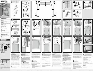
You need · Potrzebujecie · Szüksége van · Potrebujete
Potřebujete · Budete potrebovať · Sie benötigen:
Contents · Zawartość · Tartalom · Vsebina · Obsah
Obsah · Inhalt:
ALUMINIUM INSECT
DOOR SCREEN
IAN 43011
1 4 9 12 15
2 5 10 13 16
3 6
7
11 14
A
P1
T1 T2 U1
U2
Q R
S
E
F2
B
B
L
M
U1
F2N
F2
N
B O
C D
2x
J
3x
4x 9x 3x
H
3x
I
3x
V1
2x
G1
2x
2x
H
B
B - 2 cm
E
H
G1
G2
B - 2 cm
ca. 2,5 cm
B
A
F2
B
a b
V1
17
I
J
I
1
2
3
4
K
I
Q
R
H
Q
K
(150 mm)
(150 mm)
Q
4x
2x
G
G
S
U1 U1
U2
U2
V1
B
A
V1
B
V2
F1F2EB
P2
P1
B
B
F2
B
T2
T1
F1
M
4x
N
2x
O
P2
V2
2x
G2
4x
K
3x
L
2x
B
C D
B
O
O
D D
A
B
H+ 0,5 cm
ALU-INSEKTENSCHUTZ-TÜR
Montage- und Sicherheitshinweise
ALUMINIUM INSECT
DOOR SCREEN
Assembly and safety advice
SIATKA ALUMINIOWA NA
DRZWI PRZECIW OWADOM
Wskazówki dotyczące montażu oraz
bezpieczeństwa
ALUMINIJASTA VRATNA
ZAŠČITA PRED MRČESOM
Navodila za montažo in varnost
OCHRANA PROTI HMYZU
Pokyny k montáži a bezpečnostní pokyny
HLINÍK OV Á OCHRANA
PROTI HMYZU
Pokyny pre montáž a bezpečnosť
ALU SZÚNYOGHÁLÓS AJTÓ
Használati- és biztonsági utasítások
QA 273
ø 2.0 mm
ø 4.0 mm
ø 6.0 mm
43011_pow_Alu_Insektenschutz-Tuer_LB4.indd 1 16.09.13 12:47



Praat mee over dit product
Laat hier weten wat jij vindt van de Powerfix IAN 43011 Hor. Als je een vraag hebt, lees dan eerst zorgvuldig de handleiding door. Een handleiding aanvragen kan via ons contactformulier.